- 您現(xiàn)在的位置:買賣IC網(wǎng) > PDF目錄376305 > RC8650 (Electronic Theatre Controls, Inc.) VOICE SYNTHESIZER PDF資料下載
參數(shù)資料
| 型號(hào): | RC8650 |
| 廠商: | Electronic Theatre Controls, Inc. |
| 英文描述: | VOICE SYNTHESIZER |
| 中文描述: | 語音合成器 |
| 文件頁數(shù): | 12/48頁 |
| 文件大小: | 747K |
| 代理商: | RC8650 |
第1頁第2頁第3頁第4頁第5頁第6頁第7頁第8頁第9頁第10頁第11頁當(dāng)前第12頁第13頁第14頁第15頁第16頁第17頁第18頁第19頁第20頁第21頁第22頁第23頁第24頁第25頁第26頁第27頁第28頁第29頁第30頁第31頁第32頁第33頁第34頁第35頁第36頁第37頁第38頁第39頁第40頁第41頁第42頁第43頁第44頁第45頁第46頁第47頁第48頁

12
RC8650 VOICE SYNTHESIZER
RC SYSTEMS
Analog Audio Output
The analog output pins AO
0
and AO
1
are high impedance (10 k
typical) outputs from the RC8650’s internal D/A converters. When us-
ing these outputs, the addition of an external low-pass filter is highly
recommended. When laying out the printed circuit board, avoid run-
ning digital lines near the AO lines in order to minimize induced noise
in the audio path. If space permits, run a guard ground next to the
AO traces.
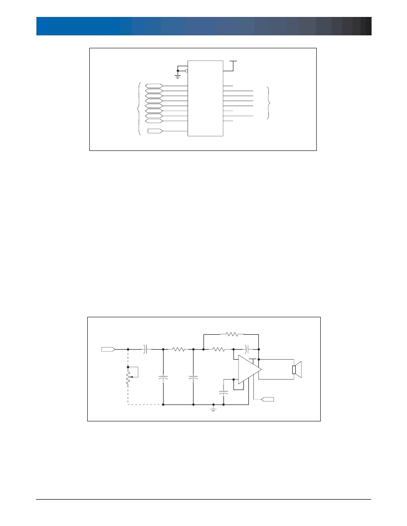
The circuit shown in Figure 1.8 is a low-pass filter/power amplifier ca-
pable of delivering 1.1 W to an 8
load, when operating from a +5 V
power supply (power output will be less when operating from +3.3 V).
Figure 1.8. 3 kHz Low-Pass Filter/Power Amplifier
The amplifier’s shutdown pin can be controlled by the TS
0
pin to mini-
mize current drain when the RC8650 is inactive.
Digital Audio Output
The digital audio pin DAOUT outputs the RC8650’s audio signal as
a digital audio stream consisting of 8 data bits per sample. The nor-
malized sampling rate for all text to speech modes and the DTMF
generator is 84 kbs (10,500 bytes/sec). The sinusoidal generator, pre-
recorded and real time audio playback mode rates are user program-
mable, so their normalized rates will vary. See the Pin Descriptions and
Audio Control Register command description for further details.
Figure 1.7. Method of Capturing Status Information for Driving External Circuitry
相關(guān)PDF資料 |
PDF描述 |
|---|---|
| RC8650L | VOICE SYNTHESIZER |
| RC86L50-0 | VOICE SYNTHESIZER |
| RC86L50-1 | VOICE SYNTHESIZER |
| RC86L50-2 | VOICE SYNTHESIZER |
| RC86L50-3 | VOICE SYNTHESIZER |
相關(guān)代理商/技術(shù)參數(shù) |
參數(shù)描述 |
|---|---|
| RC8650L | 制造商:未知廠家 制造商全稱:未知廠家 功能描述:VOICE SYNTHESIZER |
| RC865NP-101K | 制造商:SUMIDA 制造商全稱:Sumida Corporation 功能描述:Power Inductor |
| RC865NP-102K | 制造商:SUMIDA 制造商全稱:Sumida Corporation 功能描述:Power Inductor |
| RC865NP-103K | 制造商:SUMIDA 制造商全稱:Sumida Corporation 功能描述:Power Inductor |
| RC865NP-121K | 制造商:SUMIDA 制造商全稱:Sumida Corporation 功能描述:Power Inductor |
發(fā)布緊急采購,3分鐘左右您將得到回復(fù)。