- 您現(xiàn)在的位置:買賣IC網(wǎng) > PDF目錄373261 > RF1327-1 Analog IC PDF資料下載
參數(shù)資料
| 型號: | RF1327-1 |
| 英文描述: | Analog IC |
| 中文描述: | 模擬IC |
| 文件頁數(shù): | 1/2頁 |
| 文件大?。?/td> | 241K |
| 代理商: | RF1327-1 |
RF Monolithics, Inc.
RFM Europe
1999 by RF Monolithics, Inc. The stylized RFM logo are registered trademarks of RF Monolithics, Inc.
Phone: (972) 233-2903
Phone: 44 1963 251383
Fax: (972) 387-9148
Fax: 44 1963 251510
E-mail: info@rfm.com
http://www.rfm.com
RF1327-1-090600
Page 1 of 2
Electrical Characteristics
Characteristic
Sym
Notes
Minimum
Typical
Maximum
Units
Nominal Frequency
f
C
IL
2, 4, 5, 6
3, 4, 7
927.578
927.778
927.978
5.0
MHz
dB
Insertion Loss
3 dB Passband
BW
3
BW
3
2, 3, 4, 7
kHz
3 dB Reject Band
2, 3, 4, 7
±80
kHz
Rejection
at f
C
- 21.4 MHz (Image)
at f
C
- 10.7 MHz (LO)
Ultimate
Operating Case Temperature
4
40
50
dB
15
30
80
Temperature
T
C
T
O
f
O
FTC
3, 7, 8
3
-40
+85
°C
Turnover Temperature
15
25
f
C
40
°C
Turnover Frequency
MHz
ppm/°C
2
ppm/yr
nH
pF
Frequency Temperature Coefficient
0.032
10
10
3.3-3.9
Frequency Aging
External Impedance
Absolute Value during the First Year
Series Inductance
Shunt Capacitance
IfAI
L
C
1, 7
Lid Symbolization (in addition to Lot and/or Date Codes)
RFM RF1327-1
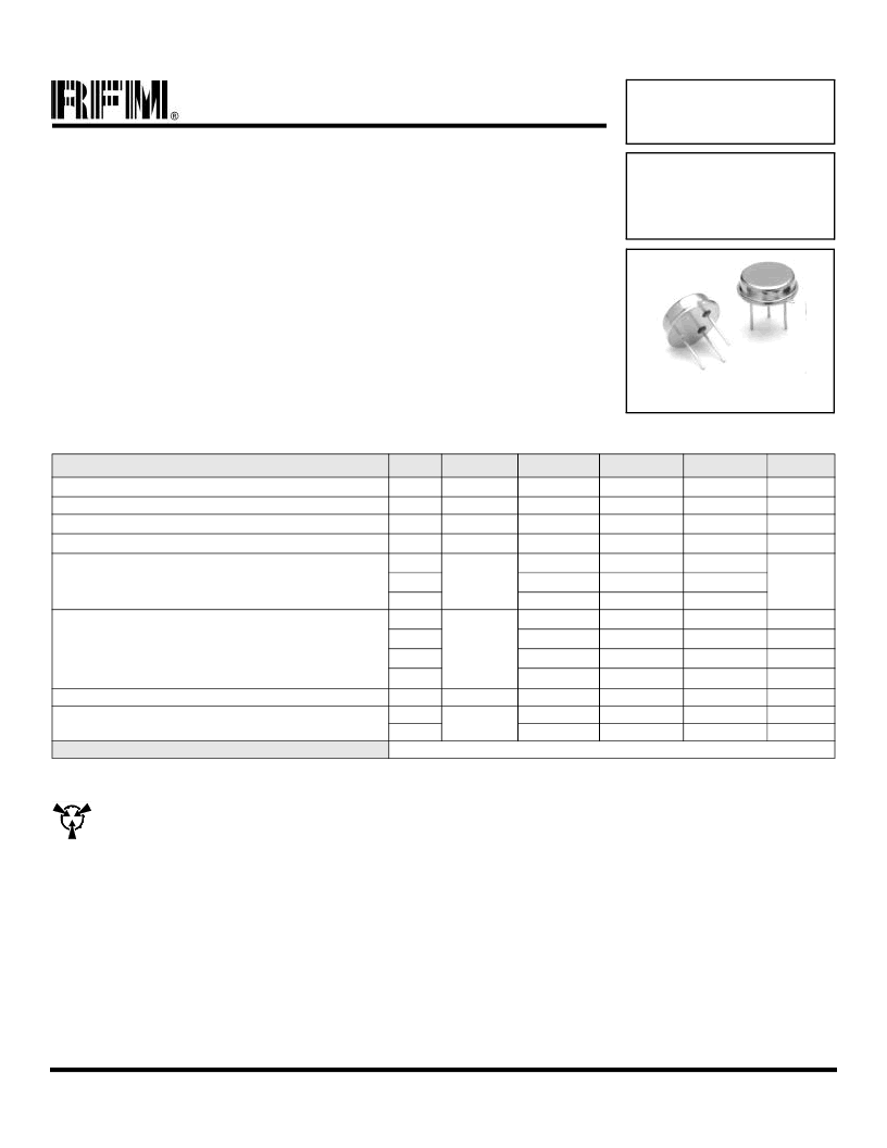
TO39-3 Case
Ideal Front-End Filter Wireless Receivers
Low-Loss, Coupled-Resonator Quartz Design
Simple External Impedance Matching
Rugged TO39 Hermetic Package
The RF1327-1 is a low-loss, compact and economical surface-acoustic-wave (SAW) filter designed to pro-
vide front-end selectivity receivers. Receiver designs using this filter include superhet with 10.7 MHz, direct
conversion and superregen. Typical applications of these FSK receivers are wireless remote-control and
security devices.
This coupled-resonator filter (CRF) uses selective null placement to provide suppression, typically greater
than 40 dB. RFM’s advanced SAW design and fabrication technology is utilized to achieve high performance
and very low loss with simple external impedance matching (not included). Quartz construction provides ex-
cellent frequency stability over a wide temperature range.
927.778 MHz
SAW Filter
RF1327-1
CAUTION: Electrostatic Sensitive Device. Observe precautions for handling.
Notes:
1. Typical test circuit is shown for TO-39 RF filters.
2. Passband and reject bands are specified in reference to f
C
.
3. All characteristics are specified over the operating temperature range and typical aging for 10 years.
4. Unless noted otherwise, all measurements are made with the filter installed in the specified test fixture. Note that insertion loss, bandwidth, and pass-
band shape are dependent on the impedance matching component values and quality. Demonstration circuits are available for confirmation of device
performance.
5. One or more of the following U.S. Patents apply: 4,454,488; 4,616,197; and other pending.
6. All equipment designs utilizing this product must be approved by the appropriate government agency prior to manufacture or sale.
7. The design, manufacturing process, and specifications of this device are subject to change without notice.
8. The turnover temperature, T
O
, is the temperature of maximum (or turnover) frequency, f
o
. The nominal frequency at any case temperature, T
C
, out-
side the operating temperature range may be calculated from: f = f
o
[1 - FTC (T
O
- T
C
)
2
].
相關(guān)PDF資料 |
PDF描述 |
|---|---|
| RF133 | RF/IF Transceiver For GSM Applications |
| RF1339B | Analog IC |
| RF137 | Transceiver For GSM Applications |
| RF1B | Fast-Recovery Rectifier Diodes (600 to 1000V) |
| RF1K4909396 | TRANSISTOR | MOSFET | MATCHED PAIR | P-CHANNEL | 12V V(BR)DSS | 2.5A I(D) | SO |
相關(guān)代理商/技術(shù)參數(shù) |
參數(shù)描述 |
|---|---|
| RF133 | 制造商:未知廠家 制造商全稱:未知廠家 功能描述:RF/IF Transceiver For GSM Applications |
| RF1334-000 | 功能描述:可復位保險絲 60V .14A-HD 10A MAX (R) RoHS:否 制造商:Bourns 電流額定值: 電阻:7.5 Ohms 最大直流電壓: 保持電流:0.1 A 安裝風格:SMD/SMT 端接類型:SMD/SMT 跳閘電流:0.6 A 引線間隔: 系列:MF-PSHT 工作溫度范圍:- 40 C to + 125 C |
| RF1335-000 | 功能描述:可復位保險絲 30V .2A-HD 10A MAX (R) RoHS:否 制造商:Bourns 電流額定值: 電阻:7.5 Ohms 最大直流電壓: 保持電流:0.1 A 安裝風格:SMD/SMT 端接類型:SMD/SMT 跳閘電流:0.6 A 引線間隔: 系列:MF-PSHT 工作溫度范圍:- 40 C to + 125 C |
| RF1336-000 | 功能描述:可復位保險絲 12V 1.5A-HD 100A MAX (R) RoHS:否 制造商:Bourns 電流額定值: 電阻:7.5 Ohms 最大直流電壓: 保持電流:0.1 A 安裝風格:SMD/SMT 端接類型:SMD/SMT 跳閘電流:0.6 A 引線間隔: 系列:MF-PSHT 工作溫度范圍:- 40 C to + 125 C |
| RF1336B | 制造商:RFM 制造商全稱:RF Monolithics, Inc 功能描述:868.35 MHz SAW Filter |
發(fā)布緊急采購,3分鐘左右您將得到回復。