- 您現(xiàn)在的位置:買賣IC網(wǎng) > PDF目錄385768 > RF2461 (RF MICRO DEVICES INC) CDMA/FM LOW NOISE AMPLIFIER/MIXER 900MHZ DOWNCONVERTER PDF資料下載
參數(shù)資料
| 型號(hào): | RF2461 |
| 廠商: | RF MICRO DEVICES INC |
| 元件分類: | 無繩電話/電話 |
| 英文描述: | CDMA/FM LOW NOISE AMPLIFIER/MIXER 900MHZ DOWNCONVERTER |
| 中文描述: | TELECOM, CELLULAR, RF AND BASEBAND CIRCUIT, QCC20 |
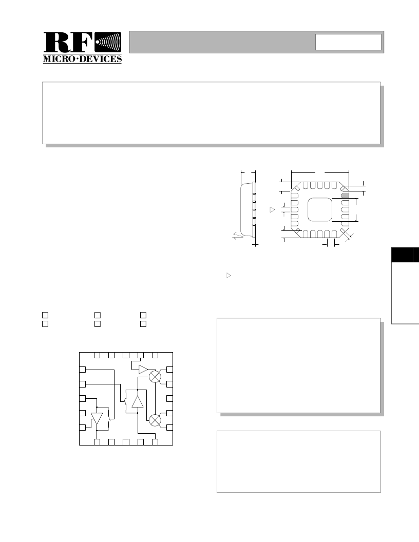
| 封裝: | 4 X 4 MM, QFN-20 |
| 文件頁數(shù): | 1/14頁 |
| 文件大小: | 365K |
| 代理商: | RF2461 |
8-123
8
F
Preliminary
Produc t Desc ription
Ordering Information
Typic al Applic ations
Features
Func tional Block Diagram
RF Micro Devices, Inc.
7625 Thorndike Road
Greensboro, NC 27409, USA
Tel (336) 664 1233
Fax (336) 664 0454
http://www.rfmd.com
Optimum Technology Matching Applied
Si BJT
GaAs HBT
Si Bi-CMOS
SiGe HBT
GaAs MESFET
Si CMOS
IF2+
15
IF2-
14
BYPASS
13
IF1+
12
IF1-
11
M
10
G
9
I
8
I
7
L
6
GND1B
5
VCC1
4
LNA IN
3
MIX GAIN
2
LNA GAIN
1
I
20
I
19
E
18
L
17
V
16
RF2461
CDMA/FM LOW NOISE AMPLIFIER/MIX ER
900 MHZ DOWNCONVER T ER
CDMA/FM Cellular Systems
Supports Dual-Mode AMPS/CDMA
Supports Dual-Mode TACS/JCDMA
General Purpose Downconverter
Commercial and Consumer Systems
Portable Battery-Powered Equipment
The RF2461 is a receiver front-end designed for the
receive section of dual-mode CDMA/FM cellular applica-
tions. It is designed to amplify and downconvert RF sig-
nals, while providing 30dB of stepped gain control range.
Features include digital control of LNA gain, mixer gain,
and power down mode. Another feature of the chip is
adjustable IIP3 of the LNA and mixer using an off-chip
current setting resistor. Noise figure, IP3, and other specs
are designed to be compatible with the IS-98B interim
standard for CDMA cellular communications. The IC is
manufactured on an advanced Silicon Germanium HBT
process and is in a 4mmx4mm, 20-pin, leadless chip car-
rier.
Complete Receiver Front-End
Stepped LNA/Mixer Gain Control
Adjustable LNA/Mixer Bias Current
Adjustable LNA/Mixer IIP3
Meets IMD Tests with Three Gain States/
Two Logic Control Lines
RF2461
CDMA/FM Low Noise Amplifier/Mixer 900MHz
Downconverter
Fully Assembled Evaluation Board
RF2461 PCBA
8
Rev A13 010607
1.00
0.90
4.00
sq.
0.60
0.24 typ
3
0.20
0.75
0.50
0.23
4 PLCS
0.50
2.10
sq.
0.65
4 PLCS
0.05
12°
MAX
Dimensions in mm.
Note orientation of package.
NOTES:
Shaded lead is Pin 1.
1
Package Warpage: 0.05 mm max.
Die Thickness Allowable: 0.305 mm max.
4
5
Pin 1 identifier must exist on top surface of package by identification
mark or feature on the package body. Exact shape and size is optional.
2
Dimension applies to plated terminal: to be measured between 0.02 mm
and 0.25 mm from terminal end.
3
Package S tyle: LCC , 20-Pin, 4 x 4
相關(guān)PDF資料 |
PDF描述 |
|---|---|
| RF2466 | 3V CDMA/FM MIXER |
| RF2469 | W-CDMA AND PCS LOW NOISE AMPLIFIER/MIXER DOWNCONVERTER |
| RF2472 | 2.4GHZ LOW NOISE AMPLIFIER WITH ENABLE |
| RF2475 | DUAL-BAND LOW NOISE AMPLIFIER/MIXER WITH FREQUENCY DOUBLER |
| RF2480 | DIRECT QUADRATURE MODULATOR |
相關(guān)代理商/技術(shù)參數(shù) |
參數(shù)描述 |
|---|---|
| RF2461_06 | 制造商:RFMD 制造商全稱:RF Micro Devices 功能描述:CDMA/FM LOW NOISE AMPLIFIER/MIXER 900MHz DOWNCONVERTER |
| RF2461_1 | 制造商:RFMD 制造商全稱:RF Micro Devices 功能描述:CDMA/FM LOW NOISE AMPLIFIER/MIXER 900MHz DOWNCONVERTER |
| RF2461PCBA-41X | 制造商:RFMD 制造商全稱:RF Micro Devices 功能描述:CDMA/FM LOW NOISE AMPLIFIER/MIXER 900MHz DOWNCONVERTER |
| RF2462-000 | 功能描述:可復(fù)位保險(xiǎn)絲 RoHS:否 制造商:Bourns 電流額定值: 電阻:7.5 Ohms 最大直流電壓: 保持電流:0.1 A 安裝風(fēng)格:SMD/SMT 端接類型:SMD/SMT 跳閘電流:0.6 A 引線間隔: 系列:MF-PSHT 工作溫度范圍:- 40 C to + 125 C |
| RF2464 | 制造商: 功能描述: 制造商:undefined 功能描述: |
發(fā)布緊急采購(gòu),3分鐘左右您將得到回復(fù)。