- 您現(xiàn)在的位置:買賣IC網(wǎng) > PDF目錄385769 > RF2488 (RF MICRO DEVICES INC) MULTI-MODE DUAL-BAND LNA MIXER PDF資料下載
參數(shù)資料
| 型號(hào): | RF2488 |
| 廠商: | RF MICRO DEVICES INC |
| 元件分類: | 衰減器 |
| 英文描述: | MULTI-MODE DUAL-BAND LNA MIXER |
| 中文描述: | RF/MICROWAVE DOWN CONVERTER |
| 文件頁數(shù): | 1/22頁 |
| 文件大?。?/td> | 483K |
| 代理商: | RF2488 |

8-123
8
F
Preliminary
Produc t Desc ription
Ordering Information
Typic al Applic ations
Features
Func tional Block Diagram
RF Micro Devices, Inc.
7625 Thorndike Road
Greensboro, NC 27409, USA
Tel (336) 664 1233
Fax (336) 664 0454
http://www.rfmd.com
Optimum Technology Matching Applied
Si BJT
GaAs HBT
Si Bi-CMOS
SiGe HBT
GaAs MESFET
Si CMOS
19
20
21
22
23
1
5
4
3
2
6
9
8
7
11
10
15
14
13
12
24
16
17
18
Low
LNA GND
GAIN SEL
Low
LNA IN
High
LNA IN
High
LNA GND
G
High
LNA VCC
H
M
BAND SEL
H
L
H
L
N
MXR VCC
IF1+
I
L
L
T
L
M
V
L
L
L
L
IF1-
IF2+
IF2-
RF2488
MULT I-MODE DUAL-BAND LNA MIX ER
TDMA/EDGE Handsets
TDMA IS-136 Handsets
GAIT Handsets
TDMA/GSM Dual-Band Handsets
GSM/DCS/EDGE Handsets
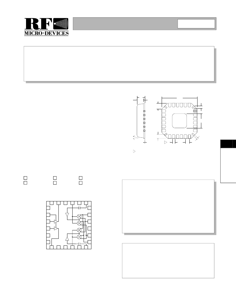
The RF2488 is a dual-band LNA/Mixer designed to sup-
port dual-band, multi-mode handset applications. The
unique dual IF outputs provide interface to two indepen-
dent IF SAW filters supporting applications that combine
IS136 with GSM, DCS or EDGE air interfaces. The device
includes four mixers, providing the ability to use two inde-
pendent IF bandwidths accessible from either the low or
high band LNAs. Each LNA has a gain bypass mode con-
trolled by the GAIN SEL pin. An image reject filter is
required between each LNA and its mixer. Power man-
agement is implemented based on a three-pin logic level
interface. Power consumption is minimized by shutting
down all but the active sections of the device.
Complete Dual-Band Front-End
Switchable LNA Gain
Low Noise and High Intercept Point
Low Current Consumption
Single 2.7V to 3.3V Power Supply
Supports Dual IF Bandwidths
RF2488
RF2488 PCBA
Multi-Mode Dual-Band LNA Mixer
Fully Assembled Evaluation Board
8
Rev A0 010905
NOTES:
Shaded Pin is Lead 1.
1
Dimension applies to plated terminal: to be measured between 0.02 mm
and 0.25 mm from terminal end.
Pin 1 identifier must exist on top surface of package by identification
mark or feature on the package body. Exact shape and size is optional.
Package Warpage: 0.05 mm max.
Die Thickness Allowable: 0.305 mm max.
4
5
2
3
12°
max
1.00
0.85
.80
.65
.05
.01
.23
.13
4 PLCS
4.00
sq.
.60
.50
.40
.28
2
.55
.30
.45
.20
4 PLCS
2.25
Package S tyle: LCC , 24-Pin, 4 x 4
相關(guān)PDF資料 |
PDF描述 |
|---|---|
| RF2489 | DUAL-BAND/TRI-MODE CDMA LOW NOISE AMPLIFIER/MIXER |
| RF2492 | DUAL-BAND LOW NOISE AMPLIFIER/MIXER |
| RF2494 | HIGH FREQUENCY LNA/MIXER |
| RF2495 | 900MHZ 3V LOW CURRENT LNA/MIXER |
| RF2504 | VCO/HIGH-ISOLATION BUFFER AMPLIFIER |
相關(guān)代理商/技術(shù)參數(shù) |
參數(shù)描述 |
|---|---|
| RF2488-000 | 制造商:TE Connectivity 功能描述:TRF250-090UT - Bag |
| RF2489 | 制造商:RFMD 制造商全稱:RF Micro Devices 功能描述:DUAL-BAND/TRI-MODE CDMA LOW NOISE AMPLIFIER/MIXER |
| RF2489_07 | 制造商:RFMD 制造商全稱:RF Micro Devices 功能描述:DUAL-BAND/TRI-MODE CDMA LOW NOISE AMPLIFIER/MIXER |
| RF2489-000 | 制造商:TE Connectivity 功能描述:TRF250-110UT - Bag |
| RF2489PCBA-41X | 制造商:RFMD 制造商全稱:RF Micro Devices 功能描述:DUAL-BAND/TRI-MODE CDMA LOW NOISE AMPLIFIER/MIXER |
發(fā)布緊急采購,3分鐘左右您將得到回復(fù)。