- 您現(xiàn)在的位置:買賣IC網(wǎng) > PDF目錄372062 > RGR1551 Fiber Optic “Light to Logic” Receiver with Clock Recovery PDF資料下載
參數(shù)資料
| 型號: | RGR1551 |
| 英文描述: | Fiber Optic “Light to Logic” Receiver with Clock Recovery |
| 中文描述: | 光纖“光的邏輯”接收機時鐘恢復 |
| 文件頁數(shù): | 3/6頁 |
| 文件大?。?/td> | 101K |
| 代理商: | RGR1551 |
414
Functional Description
Design
The receiver contains an InGaAsP
photodetector, transimpedance
amplifier, and interface amplifier
circuit, including a clock recovery
and data retiming function. It is
designed with a multimode fiber
pigtail to allow maximum
flexibility in connector options.
The interface amplifier is ac
coupled to the preamplifier
circuit.
Terminating the Outputs
The data outputs of the RGR1551
are PECL compatible. Care
should be taken to match termin-
ation impedances to the intercon-
nect to minimize reflection
effects. In order to balance the
drive currents drawn from the
module, all serial data outputs
(DATA and DATA, CLOCK and
CLOCK) should be terminated
identically, even if only one
output is used. This will lower the
power supply noise generated by
the receiver and improve
performance at low optical input
power levels.
Power Supplies
The RGR1551 will operate to
specifications with a single +5 V
power supply (Pin 10 grounded).
The –5 V PIN bias is provided to
maintain functional compatibility
with second sources.
Circuit Layout
The RGR1551 uses very high
bandwidth circuitry to achieve its
high level of performance. Care
must be taken to ensure stable
operation. The use of ground
planes and transmission line
interconnects is required. The use
of a standard evaluation board is
highly recommended for those
users who are not familiar with
these techniques.
Signal traces should conform to
ECL design rules to prevent
reflections and ringing from
degrading performance. Useful
guidelines are contained in ECL
manufacturer design manuals.
Manufacturing
The fiber pigtail on the device
requires normal fiber handling
considerations. Care should be
taken to avoid tight bends as well
as excessive tension on the fiber
pigtail.
The allowable temperature range
for the RGR1551 is limited by the
material used in the pigtail.
Exposure to temperatures over
+85
°
C is not recommended. Low
profile sockets or hand soldering
are recommended for this part.
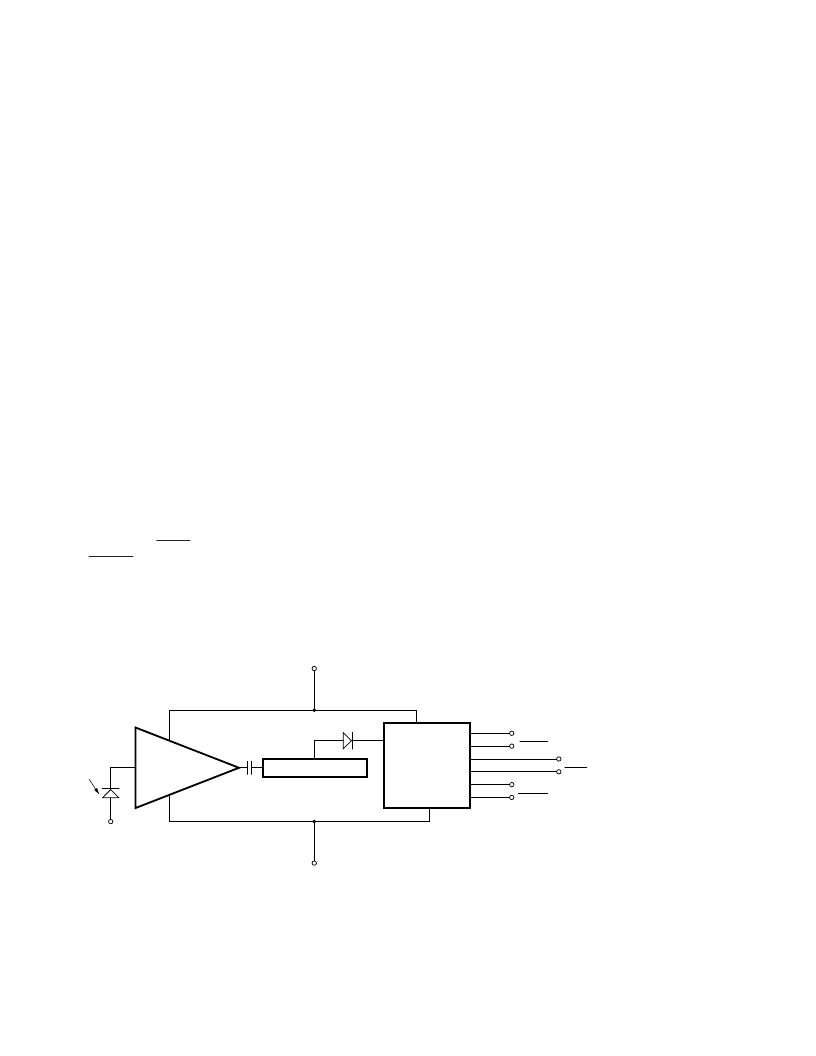
Figure 1. Block Diagram.
TRANSIMPEDANCE
AMPLIFIER
LOW PASS FILTER
PLL
CLOCK AND
DATA RECOVERY
V
CC
(+5 V)
GND (0 V)
ALARM
ALARM
DATA
DATA
CLOCK
CLOCK
V
NEG
(-5 V OR GROUND)
MID AMPLIFIER
相關PDF資料 |
PDF描述 |
|---|---|
| RGR1551-DN | Fiber Optic “Light to Logic” Receiver with Clock Recovery |
| RGR1551-FP | Fiber Optic “Light to Logic” Receiver with Clock Recovery |
| RGR1551-SC | Fiber Optic “Light to Logic” Receiver with Clock Recovery |
| RGR1551-ST | Fiber Optic “Light to Logic” Receiver with Clock Recovery |
| RGR2622 | Fiber Optic “Light to Logic” Receiver with Clock Recovery |
相關代理商/技術參數(shù) |
參數(shù)描述 |
|---|---|
| RGR1551DN | 制造商:未知廠家 制造商全稱:未知廠家 功能描述:FIBER OPTIC RECEIVER |
| RGR1551-DN | 制造商:AGILENT 制造商全稱:AGILENT 功能描述:Fiber Optic “Light to Logic” Receiver with Clock Recovery |
| RGR1551FP | 制造商:未知廠家 制造商全稱:未知廠家 功能描述:FIBER OPTIC RECEIVER |
| RGR1551-FP | 制造商:AGILENT 制造商全稱:AGILENT 功能描述:Fiber Optic “Light to Logic” Receiver with Clock Recovery |
| RGR1551SC | 制造商:未知廠家 制造商全稱:未知廠家 功能描述:FIBER OPTIC RECEIVER |
發(fā)布緊急采購,3分鐘左右您將得到回復。