- 您現(xiàn)在的位置:買賣IC網(wǎng) > PDF目錄368518 > RMDM-9SL1A-A30 (ITT Corporation) Micro-D Metal Shell - .050 Contact Spacing PDF資料下載
參數(shù)資料
| 型號(hào): | RMDM-9SL1A-A30 |
| 廠商: | ITT Corporation |
| 英文描述: | Micro-D Metal Shell - .050 Contact Spacing |
| 中文描述: | 微三維金屬外殼- .050聯(lián)系間距 |
| 文件頁數(shù): | 5/11頁 |
| 文件大小: | 318K |
| 代理商: | RMDM-9SL1A-A30 |
Micro-D Metal Shell - .050" Contact Spacing
MDM
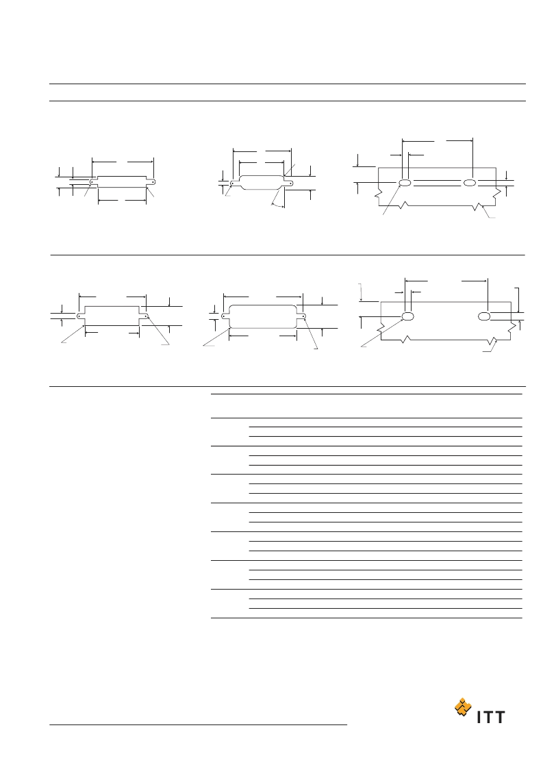
Panel Cutouts
11
www.ittcannon.com
Dimensions shown in inch (mm)
Specifications and dimensions subject to change
+ +
+ +
+ +
+ +
Shell Sizes 9 thru 51
Shell Size 100
Figure 1
Front Mounting
D
TYP.
D
TYP.
B
C
C
A
A
B
.100
(2.54)
R TYP.
.450±.002
(11.43±0.05)
FULL R.
(TYP.)
C
.030 (0.76) TYP.
D
PANEL REF.
)
.118
(3.00
1.805
(45.85
.015 (0.38)
R. MAX (TYP.)
FULL R. (TYP.)
FULL R. (TYP.)
FULL R. (TYP.)
PANEL REF.
)
.118
(3.00
)
.118
(3.00
)
)
+
.005
-.000
1.805
(45.85
)
1.805
(45.85
)
.125
(3.18
)
1.456
(36.98
)
+
-0.10
.361
(9.17
)
1.520
(38.61
)
.401
(10.18
.450
+
_.002
(11.43
+
_0.05)
.030
(0.76) TYP.
)
.015 (0.38)R.
MAX.(TYP)
FULL R.
(TYP.)
FULL R. (TYP.)
26/27TYP
Figure
2
R
e
a
r Mounting
Figure
3
Ed
ge
b
o
a
r
d
Mounting
Figure 1
Front Mounting
Figure
2
R
e
a
r Mounting
Figure
3
Ed
ge
b
o
a
r
d
Mounting
NOTE: See page 13 for rear panel mounting configuration.
+
0.13
-0.00
.005
+
0.13
+
+
-.004
+
0.10
-0.00
+
-.004
.005
+
+
-0.13
+
-0.10
+
-.004
+
-0.10
+
-.004
+
-.005
+
-0.13
+
-.005
+
-0.13
+
-.005
+
-0.13
+
-.005
+
-0.13
Shell
Size
Cutout
Figure
1
2
3
1
2
3
1
2
3
1
2
3
1
2
3
1
2
3
1
2
3
.408
.401
-
.558
.551
-
.708
.701
-
.808
.801
-
.958
.951
-
1.108
1.101
-
1.058
1.051
-
.271
.252
-
.271
.252
-
.271
.252
-
.271
.252
-
.271
.252
-
.271
.252
-
.315
.295
.570
.570
.570
.720
.720
.720
.870
.870
.870
.970
.970
.970
1.120
1.120
1.120
1.270
1.270
1.270
1.220
1.220
1.220
.089
.089
.089
.089
.089
.089
.089
.089
.089
.089
.089
.089
.089
.089
.089
.089
.089
.089
.089
.089
.089
9
15
21
25
31
37
51
A
+.004
-.000
B
+.004
-.000
C
+.005
-.000
D
+.005
-.000
For 9-51 Shell Sizes
NOTES:
1. Front panel mounting is the preferred mounting
method. Front panel mounting dimensions
(figure 1) will accommodate either #2-56 screws
or jackpost hardware.
2. Rear panel mount dimensions (figure 2) will
accommodate #2-56 screw hardware only.
When mounting the connector with rear panel
mount jackpost see the panel cut-out
dimensions.
3. Edgeboard mounting bracket (figure 3) uses #2-
56 screws. Dimension .450+/-.002 (11.43+/-
0.05) locates the MDM receptacle flush with the
end of the board.
For 100 Shell Size
NOTES:
1. Front mounting is the preferred mounting
method. Front panel mounting dimensions
(figure 1) will accommodate either #4-40 screws
or jackpost hardware.
2. Rear panel mount dimensions (figure 2) will
accommodate #4-40 screw hardware only see
the panel cut-out dimensions.
3.Edgeboard mounting bracket (figure 3) uses #4-
40 screws. Dimension .450+/-.002 (11.43+/-
0.05) locates the MDM receptacle flush with the
end of the board.
相關(guān)PDF資料 |
PDF描述 |
|---|---|
| RMDM-7P2SH1B1-A30 | Micro-D Metal Shell - .050 Contact Spacing |
| RMDM-7P2SH1M-A174 | Micro-D Metal Shell - .050 Contact Spacing |
| RMDM-7P2SH1M-A30 | Micro-D Metal Shell - .050 Contact Spacing |
| RMDM-7P2SL001A-A174 | Micro-D Metal Shell - .050 Contact Spacing |
| RMDM-7P2SL001A-A30 | Micro-D Metal Shell - .050 Contact Spacing |
相關(guān)代理商/技術(shù)參數(shù) |
參數(shù)描述 |
|---|---|
| RMDM-9SL1B1-A174 | 制造商:ITT 制造商全稱:ITT Industries 功能描述:Micro-D Metal Shell - .050 Contact Spacing |
| RMDM-9SL1B1-A30 | 制造商:ITT 制造商全稱:ITT Industries 功能描述:Micro-D Metal Shell - .050 Contact Spacing |
| RMDM-9SL1M-A174 | 制造商:ITT 制造商全稱:ITT Industries 功能描述:Micro-D Metal Shell - .050 Contact Spacing |
| RMDM-9SL1M-A30 | 制造商:ITT 制造商全稱:ITT Industries 功能描述:Micro-D Metal Shell - .050 Contact Spacing |
| RMDM-9SS001A-A174 | 制造商:ITT 制造商全稱:ITT Industries 功能描述:Micro-D Metal Shell - .050 Contact Spacing |
發(fā)布緊急采購,3分鐘左右您將得到回復(fù)。