- 您現(xiàn)在的位置:買賣IC網(wǎng) > PDF目錄373295 > RN200CHOKEKIT CHOKE KIT RN 200 PDF資料下載
參數(shù)資料
| 型號: | RN200CHOKEKIT |
| 英文描述: | CHOKE KIT RN 200 |
| 中文描述: | 扼流圈盒護(hù)士200 |
| 文件頁數(shù): | 5/18頁 |
| 文件大?。?/td> | 789K |
| 代理商: | RN200CHOKEKIT |

4
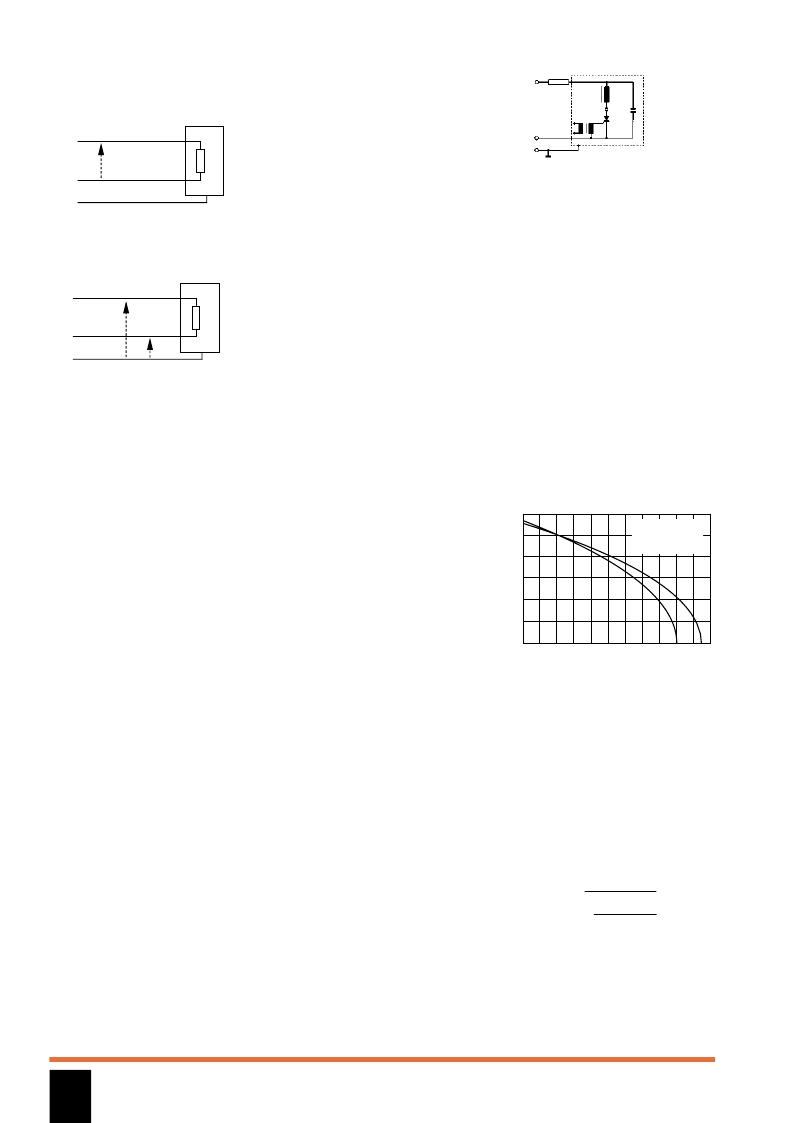
parasitic capacitance) along the earth path
and return along the phases (Figure 6).
Figure 5.
Differential mode interference
(V
DM
)
Figure 6.
Common mode interference
(V
CM
)
Suppressing interference
Interference can be reflected towards its
source by incorporating an LC network in
the noise path. This prevents interference
energy from leaving a suppressed device
and entering the power supply line. An
efficient inductor-capacitor combination to
protect against line-conducted
interference consists of:
series inductances in the interference
paths
Cx capacitors between phase and
neutral
Cy capacitors between phases and
earth
Three main types of chokes may be used
for this purpose:
current-compensated - with multiple
windings to avoid saturation (loss of
effective inductance) of the core
material
saturating chokes - which are ideal for
reducing fast current changes
rod-cored chokes - which present a
constant inductance even at high
currents
Current-compensated chokes
(RN & RD Series)
This type of component consists of a ring
core with two or more windings, potted in
a plastic housing. It is used to attenuate
common-mode or asymmetric (P/N
E)
interference signals, by being connected
in series with the phase and neutral lines
of an AC powerline input. The magnetic
fields produced by this winding technique
cancel each other out. Full inductance is
only presented to interference signals
which flow asymmetrically from
phase/neutral to earth. Symmetrical
components of the noise are also
attenuated by the leakage inductance of
the windings. The impedance of the choke
at powerline frequencies is therefore
negligible, resulting in practically zero
voltage drop. These chokes are typically
used in conjunction with suppression
capacitors as follows:
in phase-angle control circuits where the
desired degree of suppression cannot be
achieved by saturating chokes alone
for suppressing high interference levels
from ultrasonic generators, fast rectifiers,
switched mains equipment etc
for suppressing equipment with no earth
connection
for input filters to protect digital circuitry
from mains-borne interference
Saturating chokes
(RI Series)
Saturating-type chokes change
impedance at the moment of switching,
and can be used to attenuate differential-
mode or symmetrical (P
N) interference,
as generated by phase angle control
devices such as thyristors and triacs.
Interference levels can be brought within
the limits of national and international
regulations by using these chokes in
conjunction with appropriate suppression
capacitors. For optimum attenuation,
chokes must be connected as close as
possible to the semiconductor switching
device. A simple single-stage suppression
circuit is shown in Figure 7; this can be
made into a dual-stage filter by the load
itself and one additional capacitor.
Rod-cored chokes
(RF Series)
In contrast to saturating types, rod-cored
chokes present a constant inductance.
They are also suitable for attenuating
differential-mode or symmetrical (P
N)
interference, particularly lower frequency
interference up to around 500kHz. Single
and dual rod-cored chokes are ideal for
the construction of RFI suppression filters
for the 150kHz frequency region of
EN 50081.
Operating current
The maximum operating current for
components in this catalogue is specified
at an ambient temperature of 40C (Fig 8).
Figure 8.
Maximum permissible current
as a function of ambient temperature
Because Schaffner chokes are
manufactured to meet the IEC 68 climate
class (HMF, HFK, GFK and GLF classes),
the maximum internal temperature
reached in the choke is in the region of
100 to 125C. (Maximum ambient
temperature is 100 to 125C.) The formula
below provides the relationship between
ambient temperature and permissible
current loading:
I
perm
= I
nom.
√
max.
–
ambient
max.
– 40
V
DM
Line
Neutral
Earth
V
CM
V
CM
Line
Neutral
Earth
Load
P
N
E
IT
RI
C
Figure 7.
Saturating choke in series with a
thyristor
120
100
80
60
40
20
0
70
C
Nominal current
(100%)
at 40C
ambient temperature
80
90 100 110 120 130
60
%
50
40
30
20
相關(guān)PDF資料 |
PDF描述 |
|---|---|
| RN2010 | TRANSISTOR | 50V V(BR)CEO | 100MA I(C) | TO-92 |
| RN2011 | TRANSISTOR | 50V V(BR)CEO | 100MA I(C) | TO-92 |
| RN2101F | TRANSISTOR | 50V V(BR)CEO | 100MA I(C) | SOT-416 |
| RN2102F | TRANSISTOR | 50V V(BR)CEO | 100MA I(C) | SOT-416 |
| RN2103F | TRANSISTOR | 50V V(BR)CEO | 100MA I(C) | SOT-416 |
相關(guān)代理商/技術(shù)參數(shù) |
參數(shù)描述 |
|---|---|
| RN2010 | 制造商:未知廠家 制造商全稱:未知廠家 功能描述:TRANSISTOR | 50V V(BR)CEO | 100MA I(C) | TO-92 |
| RN2010(F) | 制造商:Toshiba America Electronic Components 功能描述: |
| RN2011 | 制造商:未知廠家 制造商全稱:未知廠家 功能描述:TRANSISTOR | 50V V(BR)CEO | 100MA I(C) | TO-92 |
| RN2011(F) | 制造商:Toshiba America Electronic Components 功能描述: |
| RN202 | 制造商:未知廠家 制造商全稱:未知廠家 功能描述:Current-compensated Chokes |
發(fā)布緊急采購,3分鐘左右您將得到回復(fù)。