- 您現(xiàn)在的位置:買賣IC網(wǎng) > PDF目錄373335 > RX1110 Analog IC PDF資料下載
參數(shù)資料
| 型號: | RX1110 |
| 英文描述: | Analog IC |
| 中文描述: | 模擬IC |
| 文件頁數(shù): | 2/4頁 |
| 文件大小: | 316K |
| 代理商: | RX1110 |
The RX Series SMT Hybrid ASH Receivers
RF Monolithics, Inc.
Phone: (972) 233-2903
Fax: (972) 387-8148
E-mail: info@rfm.com
http:\\www.rfm.com
RX1110-121198
Page 2 of 4
1998 by RF Monolithics, Inc. The stylized RFM logo and RFM are registered trademarks of RF Monolithics, Inc.
CAUTION: Electrostatic Sensitive Device. Observe precautions for handling.
Notes:
1. Unless noted otherwise, specifications apply over the entire specified operating temperature and voltage ranges.
2. One or more of the following United States patents apply: 4,454,488; 4,616,197; 4,749,964; 4,902,925. Other patents are pending.
3. Typically, equipment utilizing this device requires emissions testing and government approval, which is the responsibility of the
equipment manufacturer.
4. The design, manufacturing process, and specifications of this device are subject to change without notice.
5. A variety of on-off-keyed(OOK) pulse modulation schemes are possible since digital decoding is an external function (not included in
the ASH receiver).
6. These parameters apply over the absolute minimum operating passband which is referenced to f
C
.
7. With interfering signal matched to the receiver modulation and code. See “Typical Modulated Interference Rejection” for a more
detailed view.
8. Sample repetition rates greater than 1 MHz are available in custom versions. Contact RFM for details.
9. Baseband bandwidths and data rates are available to 140 kHz and 56 kHz, respectively, in custom versions. Contact RFM for
details.
10. The default comparator threshold (with terminal 5 not connected) is optimized for low duty-cycle, or “bursty” data and eliminates
noise output when there is no RF signal. The override threshold (with terminal 5 connected to ground) is optimized for continuous
data.
11. The ASH receiver is designed to drive a single CMOS load.
12. For ESD protection.
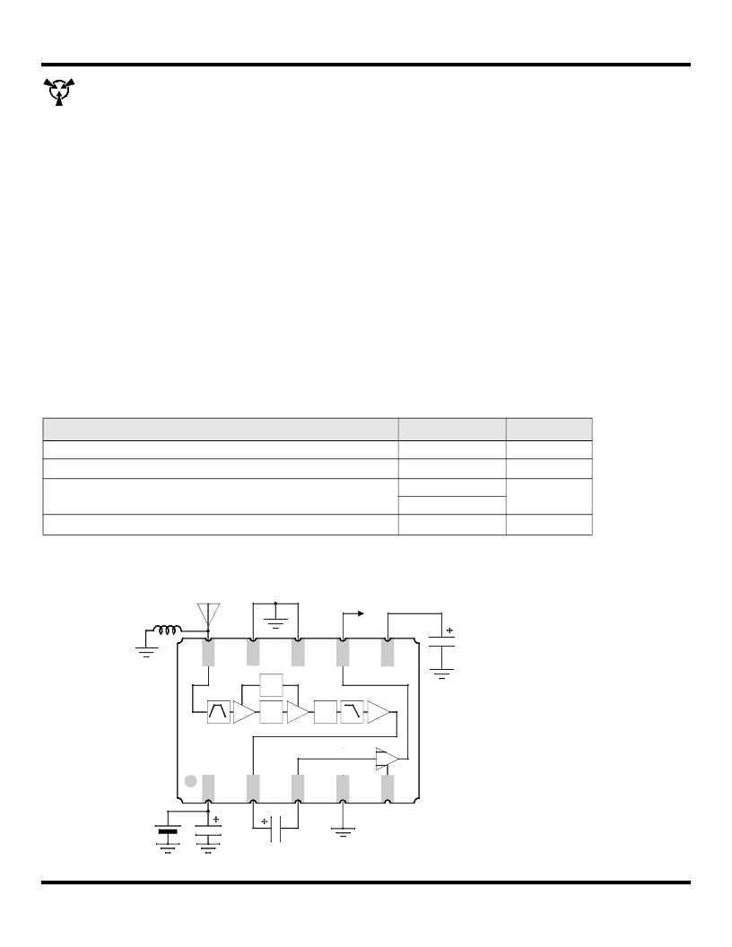
Block Diagram and Electrical Connections
Absolute Maximum Ratings
Rating
Value
Units
Incident RF Power
+10
dBm
Power Supply Voltage (V
CC
to Ground)(Observe ESD Precautions)
ESD (100 pF, 1.5 kW)
-0.3 to +4.0
VDC
Terminals 2, 3, or 7 to Ground
±2000
V
All Other Terminals to Ground
±300
Case Temperature
1
-40 to +100
°C
T
50 ohm Antenna
+3V
10 uF
0.1 to 10 uF
1 uF
Pulse
Line
LPF
RF
Amp.
RF
Amp.
SAW BPF
Comparator
AM
Detector
10
9
8
7
6
5
4
3
2
1
RF Input
Gnd
Gnd
Data Output
RVoltage
Vcc
BOutput
CoInput
Gnd
Override
Note 12
相關(guān)PDF資料 |
PDF描述 |
|---|---|
| RX1120 | Analog IC |
| RX1214B130Y | NPN Microwave power transistor(NPN 微波功率晶體管) |
| RX1214B80W | NPN Microwave power transistor(NPN 微波功率晶體管) |
| RX1214B150W | Bipolar NPN UHF/Microwave Transisitor |
| RX1214B170W | Microwave power transistor(微波功率晶體管) |
相關(guān)代理商/技術(shù)參數(shù) |
參數(shù)描述 |
|---|---|
| RX1120 | 制造商:未知廠家 制造商全稱:未知廠家 功能描述:Analog IC |
| RX1-121.500-10 | 制造商:RADIOMETRIX 制造商全稱:RADIOMETRIX 功能描述:VHF Narrow Band FM Transmitter and Receiver |
| RX114005 | 制造商:MA-COM 制造商全稱:M/A-COM Technology Solutions, Inc. 功能描述:Power PCB Relay |
| RX114005C | 制造商:MA-COM 制造商全稱:M/A-COM Technology Solutions, Inc. 功能描述:Power PCB Relay |
| RX114012 | 制造商:TE Connectivity 功能描述:PCB Relay SPDT 12A 12Vdc |
發(fā)布緊急采購,3分鐘左右您將得到回復(fù)。