- 您現(xiàn)在的位置:買賣IC網(wǎng) > PDF目錄297342 > S5649LSV-FREQ3 TCVCXO, CLIPPED SINE OUTPUT, 16 MHz - 20 MHz PDF資料下載
參數(shù)資料
| 型號: | S5649LSV-FREQ3 |
| 元件分類: | XO, clock |
| 英文描述: | TCVCXO, CLIPPED SINE OUTPUT, 16 MHz - 20 MHz |
| 文件頁數(shù): | 1/2頁 |
| 文件大小: | 84K |
| 代理商: | S5649LSV-FREQ3 |

DS-168
REV C
Technical Data
SaRonix
S5600 Series
Frequency Range:
8 MHz to 20 MHz
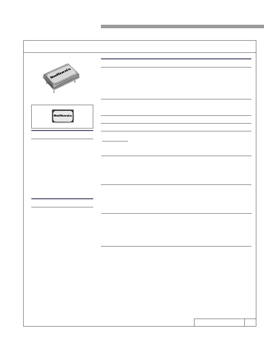
ACTUAL SIZE
This TCVCXO is comprised of a quartz
crystal and an integrated circuit. The IC
contains the oscillator, the temperature
compensation and the modulation func-
tions. The components are assembled on
a hybrid circuit and protected by a
metal cover that also provides shielding.
An external voltage is applied for cali-
bration, adjustment
and modulation.
The TCVCXO is available with differ-
ent stability, pullability or modulation
values.
Frequency Stability:
Temperature Range:
Operating:
Storage:
Supply Voltage:
+5V ±5%
Supply Current:
Clipped Sinewave
Level:
Load:
1.0V min peak-to-peak, 8 to 13 MHz
0.8V min peak-to-peak, 13+ to 16 MHz
0.7V min peak-to-peak, 16+ to 20 MHz
10K // 10 pF
2.65mA typ, 3mA max
Frequency Adjustment:
Rated Control Voltage:
Relative Pull Range:
Control V Input Impedance:
Modulation Bandwidth:
Transfer Function:
Applications & Features
Cellular Telephone (GSM, TDMA,
CDMA, etc.)
Mobile and Portable Radio/Telephone
Communication Transceivers
Cordless Telephone
Also available with very low phase
noise (consult factory)
5 Volt operation
Low profile 3.8mm high package
-30 to +80°C
-45 to +100°C
Output:
MIL-STD-883, Method 2002, Condition B
MIL-STD-883, Method 2003
MIL-STD-202, Method 211, Conditions A and C
MIL-STD-883, Method 2007, Condition A
MIL-STD-202, Method 215
MIL-STD-202, Method 210, Condition A, B or C
Mechanical:
Shock:
Solderability:
Terminal Strength:
Vibration
Solvent Resistance:
Resistance to Soldering Heat:
Environmental:
Thermal Shock:
MIL-STD-883, Method 1011, Condition A
0.5V to 4.5VDC
±8.5, 15, 40 and >40ppm (VC = 2.5V ±2V)
50k
min
10kHz min
Frequency Increases when Control Voltage Increases
Description
SaRonix
141 Jefferson Drive Menlo Park, CA 94025 USA 650-470-7700 800-227-8974 Fax 650-462-9894
TCVCXO
5V, Clipped Sinewave, Tight Stability
vs. temperature: ±1.5, ±2.5, ±4, ±8ppm max, see part numbering guide
vs. aging: ±3.0ppm (125°C, 1000 hrs)
vs. supply voltage: ±0.2ppm (5V ±5%)
vs. load: ± 0.2 ppm (10 pF to 20pF)
vs. hysteresis: ±0.3 ppm (temp change at rate of 1°C per minute)
vs. temp cycle: ± 0.1 ppm (10 cycles, min to max storage temp)
perturbations: 0.5 ppm peak-to-peak max
-50 dBc/Hz min @ 1Hz offset from carrier
-80 dBc/Hz min @ 10Hz
-120 dBc/Hz min @ 100Hz
-150 dBc/Hz min @ 1kHz
-155 dBc/Hz min @ 10kHz
-155 dBc/Hz min @ 100kHz
Phase Noise:
相關(guān)PDF資料 |
PDF描述 |
|---|---|
| S582-11-272-10-005414 | BGA272, IC SOCKET |
| S5PMS-M3/86A | 1.8 A, 1000 V, SILICON, RECTIFIER DIODE, TO-277A |
| S5S2-H | 2000 MHz - 6000 MHz RF/MICROWAVE SGL POLE FIVE THROW SWITCH, 1.8 dB INSERTION LOSS |
| S5S2-RC | 2000 MHz - 6000 MHz RF/MICROWAVE SGL POLE FIVE THROW SWITCH, 1.8 dB INSERTION LOSS |
| S5S5-5-H | 2000 MHz - 12000 MHz RF/MICROWAVE SGL POLE FIVE THROW SWITCH, 2.8 dB INSERTION LOSS |
相關(guān)代理商/技術(shù)參數(shù) |
參數(shù)描述 |
|---|---|
| S565PC | 制造商:Starrett Company 功能描述:DRIVE PIN PUNCH 制造商:Starrett Company 功能描述:DRIVE PIN PUNCH; Kit Contents:8-Pcs of 1/16", 3/32", 1/8", 5/32", 3/16", 7/32", 1/4", 5/16" Pin Punch ;RoHS Compliant: NA |
| S5661 | 制造商:BOTHHAND 制造商全稱:Bothhand USA, LP. 功能描述:T3/DS3/E3/STS-1 TRANSFORMER |
| S5662 | 制造商:BOTHHAND 制造商全稱:Bothhand USA, LP. 功能描述:T3/DS3/E3/STS-1 TRANSFORMER |
| S5663 | 制造商:BOTHHAND 制造商全稱:Bothhand USA, LP. 功能描述:T3/DS3/E3/STS-1 TRANSFORMER |
| S5664 | 制造商:MERKLE-KORFF INDUSTRIES 功能描述:S5664 |
發(fā)布緊急采購,3分鐘左右您將得到回復(fù)。