- 您現(xiàn)在的位置:買賣IC網(wǎng) > PDF目錄368612 > S5K437CA (SAMSUNG SEMICONDUCTOR CO. LTD.) 1/4 Optical Size 640x480 (VGA) 2.8V CMOS Image Sensor PDF資料下載
參數(shù)資料
| 型號(hào): | S5K437CA |
| 廠商: | SAMSUNG SEMICONDUCTOR CO. LTD. |
| 英文描述: | 1/4 Optical Size 640x480 (VGA) 2.8V CMOS Image Sensor |
| 中文描述: | 1 / 4光學(xué)尺寸640 × 480(VGA)的2.8V的CMOS圖像傳感器 |
| 文件頁(yè)數(shù): | 23/36頁(yè) |
| 文件大小: | 285K |
| 代理商: | S5K437CA |
第1頁(yè)第2頁(yè)第3頁(yè)第4頁(yè)第5頁(yè)第6頁(yè)第7頁(yè)第8頁(yè)第9頁(yè)第10頁(yè)第11頁(yè)第12頁(yè)第13頁(yè)第14頁(yè)第15頁(yè)第16頁(yè)第17頁(yè)第18頁(yè)第19頁(yè)第20頁(yè)第21頁(yè)第22頁(yè)當(dāng)前第23頁(yè)第24頁(yè)第25頁(yè)第26頁(yè)第27頁(yè)第28頁(yè)第29頁(yè)第30頁(yè)第31頁(yè)第32頁(yè)第33頁(yè)第34頁(yè)第35頁(yè)第36頁(yè)
1/4 INCH VGA CMOS IMAGE SENSOR
S5K437CX
19
OPERATION DESCRIPTION
1. Output Data Format
1-1. Main Clock Divider
All the data output and sync signals are synchronized to data clock output (
DCLK
). It is generated as the main
clock input (
MCLK
) is divided. The dividing ratio is 1, 2, 4, and 8 according to main clock dividing control register
(
mcdiv
). For 10-bit ADC and VGA resolution, dividing ratio of more than 2 is required. If ratio of 1 is used, the duty
must be within 40% to 60%.
1-2. Synchronous Signal Output
The horizontal sync (
HSYNC
) and vertical sync (
VSYNC
) signals are also available. The sync pulse width, polarity
and position are programmable on the control registers (ref. timing chart). When display mode is activated, the
sync signal outputs indicate that the output data is valid (
hsdisp
= 1) or the output rows are valid (
vsdisp
= 1).
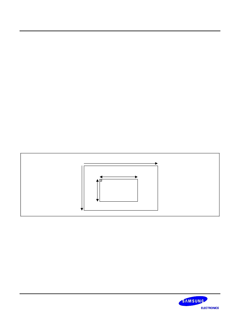
1-3. Window of Interest Control
Window of Interest (WOI) is defined as the pixel address range to be read out. The WOI can be assigned
anywhere on the pixel array. It is composed of four values: row start pointer (
wrp
), column start pointer (
wcp
),
row depth(
wrd
) and column width (
wcw
). Each value can be programmed on the control registers. For
convenience of color signal processing,
wcp
is truncated to even numbers so that the starting data of each line is
on the red and green column of Bayer pattern. Figure 4 illustrates the WOI on the displayed pixel image.
Window Of Interest
(wcp,wrp)
wcw
w
0
687
507
Figure 4. WOI definition
1-4. Vertical Mirror and Horizontal Mirror Mode Control
The pixel data are normally read out from left to right in horizontal direction and from top to bottom in vertical
direction. By changing the mirror mode, the read-out sequence can be reversed and the resulting image can be
flipped like a mirror image. Pixel data are read out from right to left in horizontal mirror mode and from bottom to
top in vertical mirror mode. The horizontal and the vertical mirror mode can be programmed on the Horizontal
Mirror Control Register (
mirch
) and Vertical Mirror Control Register (
mircv
).
1-5. Sub-sampling Control
The pixel data in sub-sampling rate can be read out in both horizontal and vertical direction. Sub-sampling can be
done in four rates : full, 1/2, 1/3 and 1/4. You can control the sub-sampling on the Sub-sampling Control
Registers,
subsr
and
subsc
. The sub-sampling is performed only in the Bayer space.
相關(guān)PDF資料 |
PDF描述 |
|---|---|
| S5K437CX01 | 1/4 Optical Size 640x480 (VGA) 2.8V CMOS Image Sensor |
| S5K437CX02 | 1/4 Optical Size 640x480 (VGA) 2.8V CMOS Image Sensor |
| S5K437CX03 | 1/4 Optical Size 640x480 (VGA) 2.8V CMOS Image Sensor |
| S5L1462B01-Q0R0 | CD and DVD playback |
| S5L1462B | CD and DVD playback |
相關(guān)代理商/技術(shù)參數(shù) |
參數(shù)描述 |
|---|---|
| S5K437CX01 | 制造商:SAMSUNG 制造商全稱:Samsung semiconductor 功能描述:1/4 Optical Size 640x480 (VGA) 2.8V CMOS Image Sensor |
| S5K437CX02 | 制造商:SAMSUNG 制造商全稱:Samsung semiconductor 功能描述:1/4 Optical Size 640x480 (VGA) 2.8V CMOS Image Sensor |
| S5K437CX03 | 制造商:SAMSUNG 制造商全稱:Samsung semiconductor 功能描述:1/4 Optical Size 640x480 (VGA) 2.8V CMOS Image Sensor |
| S5K711CA | 制造商:SAMSUNG 制造商全稱:Samsung semiconductor 功能描述:1/7 CIF CMOS Image Sensor |
| S5K711CA01 | 制造商:SAMSUNG 制造商全稱:Samsung semiconductor 功能描述:1/7 CIF CMOS Image Sensor |
發(fā)布緊急采購(gòu),3分鐘左右您將得到回復(fù)。