- 您現(xiàn)在的位置:買賣IC網(wǎng) > PDF目錄373355 > S82K-P09024 (Electronic Theatre Controls, Inc.) Switch mode Power Supply PDF資料下載
參數(shù)資料
| 型號: | S82K-P09024 |
| 廠商: | Electronic Theatre Controls, Inc. |
| 英文描述: | Switch mode Power Supply |
| 中文描述: | 開關(guān)電源 |
| 文件頁數(shù): | 18/20頁 |
| 文件大?。?/td> | 318K |
| 代理商: | S82K-P09024 |
L-22
Switch mode Power Supply
S82K
Precautions
!Caution
Be sure to connect the grounding line. Not doing so may result in
electric shock.
!WARNING
Do not attempt to disassemble the Power Supply or touch its inter-
nal parts while power is being supplied. Doing so may result in
electric shock.
Do not touch the terminals of the Power Supply within one minute
after power has been turned OFF. Doing so may result in electric
shock due to a residual voltage.
Do not touch the Power Supply Unit while power is being supplied
or immediately after power has been turned OFF. Doing so may
result in a skin burn due to high temperature of the Power Supply.
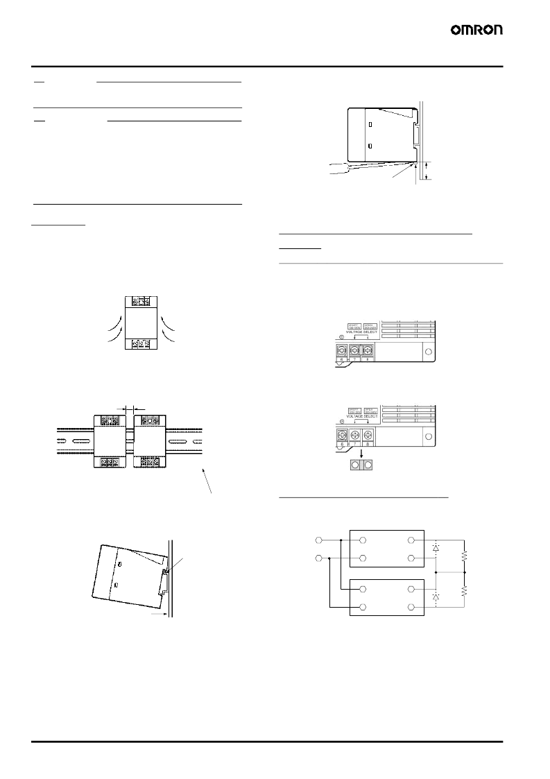
Mounting
To improve and maintain the reliability of the Power Supply over a
long period of time, adequate consideration must be given to heat
radiation.
The Power Supply is designed to radiate heat by means of natural
air-flow. Therefore, mount the Power Supply so that air flow takes
place around the Power Supply.
When mounting two or more Power Supplies side-by-side, allow at
least 10 mm spacing between them, as shown in the following illus-
tration.
Forced air-cooling is recommended.
To mount the Power Supply on a DIN track, hook portion (A) of the
Power Supply to the track and press the Power Supply toward direc-
tion (B).
To dismount the Power Supply, pull down portion (C) with a flat-blade
screwdriver and pull out the Power Supply.
When tightening the terminals, do not tighten the terminal block to a
torque greater than 75 N.
Selection of 100 or 200 VAC Input
Voltage
(S82K-
@
09024/-
@
10024/-24024/-24024T)
Select a 100 V or 200 V input by shorting or opening the Input Volt-
age Selector Terminals, as shown in the following diagram.
The default setting is 200 V.
Generating Output Voltage (
±
)
An output of
±
can be generated by using two Power Supplies as
shown below, because the Power Supply produces a floating output.
When connecting the Power Supplies in series with an operation
amplifier, connect diodes to the output terminals as shown by the
dotted lines in the figure. No diodes are required with S82K 90-W/
100-W/240-W models.
Air
10 mm min.
Short bar
(A)
(B)
C
30 mm min.
Track stopper
100 V Input
200 V Input
Remove the short bar.
Use the short bar to short-circuit
terminals 7 and 8.
+V
V
+V
V
INPUT
INPUT
相關(guān)PDF資料 |
PDF描述 |
|---|---|
| S82K-00305 | Switch mode Power Supply |
| S82K-00315 | Switch mode Power Supply |
| S82K-00324 | Switch mode Power Supply |
| S82K-00705 | Switch mode Power Supply |
| S82K-00712 | Switch mode Power Supply |
相關(guān)代理商/技術(shù)參數(shù) |
參數(shù)描述 |
|---|---|
| S82KP10024 | 制造商:OMRON INDUSTRIAL AUTOMATION 功能描述:AC/DC Power Supply Single-OUT 24V 4.2A 100W 16-Pin |
| S82K-P10024 | 制造商:未知廠家 制造商全稱:未知廠家 功能描述:Switch mode Power Supply |
| S82K-P24024 | 制造商:未知廠家 制造商全稱:未知廠家 功能描述:Switch mode Power Supply |
| S82L1024 | 制造商:OMRON INDUSTRIAL AUTOMATION 功能描述:AC/DC Power Supply Single-OUT 24V 4.6A 100W |
| S82L1524 | 制造商:OMRON INDUSTRIAL AUTOMATION 功能描述:AC/DC Power Supply Single-OUT 24V 7A 150W |
發(fā)布緊急采購,3分鐘左右您將得到回復(fù)。