- 您現(xiàn)在的位置:買賣IC網(wǎng) > PDF目錄385812 > SA1638 (NXP Semiconductors N.V.) Low voltage IF I/Q transceiver PDF資料下載
參數(shù)資料
| 型號: | SA1638 |
| 廠商: | NXP Semiconductors N.V. |
| 英文描述: | Low voltage IF I/Q transceiver |
| 中文描述: | 低電壓中頻I / Q收發(fā)器 |
| 文件頁數(shù): | 10/26頁 |
| 文件大?。?/td> | 291K |
| 代理商: | SA1638 |

Philips Semiconductors
Product specification
SA1638
Low voltage IF I/Q transceiver
1997 Sept 03
10
The overall filter response in the receive section is the sum of the
filter responses of the passive RC low-pass filter and the active
gyrator filter.
Power Down Modes
There are 4 power-on pins in the SA1638: P
ON
, P
ON
Rx, PDTx,
P
ON
PLL.
P
ON
= H powers up both voltage regulators V
REG
1 and V
REG
2. P
ON
should be set to L, if these internal voltage regulators are not to be
used.
P
ON
Rx = H powers up the receiver part.
PDTx = L powers up the transmitter part.
P
ON
PLL = H powers up the synthesizer part. As it also powers up
the first divide by 2 stage for generating the 0/90 degree phase
shifted signals for the transmit and receive mixers, it also has to be
set H if either the transmit part or the receive part is used. P
ON
PLL
= L powers down the dividers, resets the phase detector and
disconnects the current setting pin I
REF
. In P
ON
PLL = L mode, the
values in the serial input registers are still kept and the part still can
be reprogrammed as long as V
CC
DIG is present.
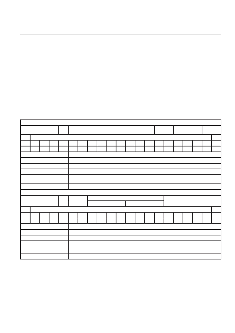
Table 3.
First data word: (shown with default values)
Definition of SA1638 Serial Registers
Address SA1638
Sub
Adr
N-Divider
Ref
÷
Reg
Charge-Pump
Reg Test
MSB
LSB
a0
a1
a2
a3
sa
n0
n1
n2
n3
n4
n5
n6
n7
n8
r0
r1
c0
c1
c2
x0
x1
1
1
1
0
0
1
1
0
0
1
0
0
0
0
0
0
1
1
1
0
0
Address:
4 bits, a0...a3, fixed to 1110
Sub:Address:
1 bit, sa, fixed to 0 for first data word
N-Divider:
9 bits, n0...n8, values 64 (00100 0000) to 511 (111111111) allowed for IF-choice, default 400
Reference Divider Register:
2 bits, r0...r1, 00 =
÷
13, 01 =
÷
26, 10 =
÷
39, 11 =
÷
52. Default: 00
Charge-Pump Register:
3 bits, c0...c2, Binary current setting factor for charge pumps, values 000 = minimum current to 111 =
maximum current, default maximum charge pump current
Test Register:
2 bits, x0...x1, default 00, see Functional Description
Second data word: (shown with default values)
Address SA1638
Sub
Adr
Status
Reg
DC Offset Register
Mode Select Register
Q-Channel
I-Channel
MSB
LSB
a0
a1
a2
a3
sa
s0
s1
q0
q1
q2
q3
i0
i1
i2
i3
t0
t1
t2
t3
t4
t5
1
1
1
0
1
1
1
0
0
0
0
0
0
0
0
0
0
0
0
0
0
Address:
4 bits, a0...a3, fixed to 1110
Sub:Address:
1 bit, sa, fixed to 1 for second data word
Status Register:
2 bits, s0 sets pin A
OUT
; s1 sets pin B
OUT
, see Functional Description
4 bits per channel, i0...i3 and q0...q3, no correction as default
i0 and q0 switches offset polarity, 0 to lower voltage, 1 to higher voltage
il...i3 and q1...q3, 000 no correction to 111 max. correction enabled
DC Offset Register:
Mode Select Register:
6 bits,
t0...t5,
000000 = normal GSM-Operation as default, see Functional Description
相關PDF資料 |
PDF描述 |
|---|---|
| SA2531B | VERSATILE SINGLE CHIP TELEPHONE WITH 14 NUMBER REPERTORY DIALLER |
| SA2531A | VERSATILE SINGLE CHIP TELEPHONE WITH 14 NUMBER REPERTORY DIALLER |
| SA2531C | VERSATILE SINGLE CHIP TELEPHONE WITH 14 NUMBER REPERTORY DIALLER |
| SA2531D | VERSATILE SINGLE CHIP TELEPHONE WITH 14 NUMBER REPERTORY DIALLER |
| SA2531E | VERSATILE SINGLE CHIP TELEPHONE WITH 14 NUMBER REPERTORY DIALLER |
相關代理商/技術參數(shù) |
參數(shù)描述 |
|---|---|
| SA1638BE | 制造商:PHILIPS 制造商全稱:NXP Semiconductors 功能描述:Low voltage IF I/Q transceiver |
| SA165A2921 0041 | 制造商:Nordic Power i Stromstad 功能描述:Bulk |
| SA165E-12U A165E089024-1 | 制造商:Nordic Power i Stromstad 功能描述: |
| SA165E-12U/A165E099005-2 | 制造商:Nordic Power i Stromstad 功能描述: |
| SA165E-24U A165E089020-3 | 制造商:Nordic Power i Stromstad 功能描述:Bulk |
發(fā)布緊急采購,3分鐘左右您將得到回復。