- 您現(xiàn)在的位置:買賣IC網(wǎng) > PDF目錄372112 > SAA6579 (NXP SEMICONDUCTORS) Radio Data System RDS demodulator PDF資料下載
參數(shù)資料
| 型號: | SAA6579 |
| 廠商: | NXP SEMICONDUCTORS |
| 元件分類: | 消費家電 |
| 英文描述: | Radio Data System RDS demodulator |
| 中文描述: | SPECIALTY CONSUMER CIRCUIT, PDIP16 |
| 封裝: | 0.300 INCH, MO-001, SOT-38-1, PLASTIC, DIP-16 |
| 文件頁數(shù): | 5/16頁 |
| 文件大小: | 116K |
| 代理商: | SAA6579 |

1997 Feb 24
5
Philips Semiconductors
Product specification
Radio Data System (RDS) demodulator
SAA6579
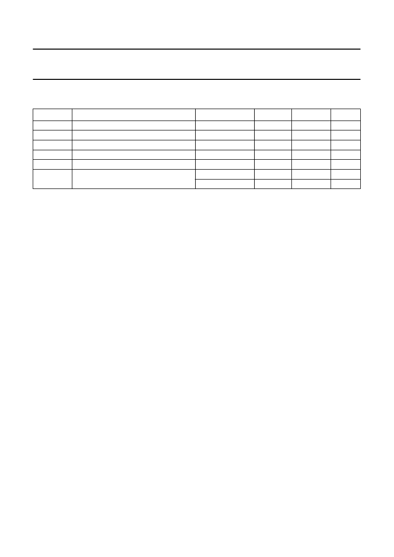
LIMITING VALUES
In accordance with the Absolute Maximum Rating System (IEC 134); ground pins 6 and 11 connected together.
Notes
1.
2.
Equivalent to discharging a 200 pF capacitor via a 0
series resistor.
Equivalent to discharging a 100 pF capacitor via a 1.5 k
series resistor.
SYMBOL
PARAMETER
CONDITIONS
MIN.
MAX.
UNIT
V
DDA
V
DDD
V
n
T
stg
T
amb
V
es
analog supply voltage (pin 5)
digital supply voltage (pin 12)
voltage on all pins; grounds excluded
storage temperature
operating ambient temperature
electrostatic handling for all pins except
pins 9 and 10
0
0
0.5
40
40
±
300
+1500
6
6
V
DDX
+ 0.5
+150
+85
3000
V
V
V
°
C
°
C
V
V
note 1
note 2
FUNCTIONAL DESCRIPTION
The SAA6579 is a demodulator circuit for RDS
applications. It contains a 57 kHz bandpass filter and a
digital demodulator to regenerate the RDS data stream out
of the multiplex signal (MPX).
Filter part
The MUX signal is band-limited by a second-order
anti-aliasing-filter and fed through a 57 kHz band-pass
filter (8th order band-pass filter with 3 kHz bandwidth) to
separate the RDS signals. This filter uses switched
capacitor technique and is clocked by a clock frequency of
541.5 kHz derived from the 4.332/8.664 MHz crystal
oscillator. Then the signal is fed to the reconstruction filter
to smooth the sampled and filtered RDS signal before it is
output on pin 8. The signal is AC-coupled to the
comparator (pin 7). The comparator is clocked with a
frequency of 228 kHz (synchronized by the 57 kHz of the
demodulator).
Digital part
The synchronous demodulator (Costas loop circuit) with
carrier regeneration demodulates the internal coupled,
digitized signal. The suppressed carrier is recovered from
the two sidebands (Costas loop). The demodulated signal
is low-pass-filtered in such a way that the overall pulse
shape (transmitter and receiver) approaches a
cosinusoidal form in conjunction with the following
Integrate and dump circuit.
The data-spectrum shaping is split into two equal parts and
handled in the transmitter and in the receiver. Ideally, the
data filtering should be equal in both of these parts.
The overall data-channel-spectrum shaping of the
transmitter and the receiver is approximately 100% roll-off.
The Integrate and dump circuit performs an integration
over a clock period. This results in a demodulated and
valid RDS signal in form of biphase symbols being output
from the integrate and dump circuit. The final stages of
RDS data processing are the biphase symbol decoding
and the differential decoding. After synchronization by
data clock RDCL (pin 16) data appears on the RDDA
output (pin 2). The output of the biphase symbol decoder
is evaluated by a special circuit to provide an indication of
good data (QUAL = HIGH) or corrupt data (QUAL = LOW).
Timing
Fixed and variable dividers are applied to the
4.332/8.664 MHz crystal oscillator to generate the
1.1875 kHz RDS clock RDCL, which is synchronized by
the incoming data. Which ever clock edge is considered
(positive or negative going edge) the data will remain valid
for 399
μ
s after the clock transition. The timing of data
change is 4
μ
s before a clock change. Which clock
transition (positive or negative going clock) the data
change occurs in, depends on the lock conditions and is
arbitrary (bit slip).
During poor reception it is possible that faults in phase
occur, then the clock signal stays uninterrupted, and data
is constant for 1.5 clock periods. Normally, faults in phase
do not occur on a cyclic basis. If however, faults in phase
occur in this way, the minimum spacing between two
possible faults in phase depends on the data being
transmitted. The minimum spacing cannot be less than
16 clock periods. The quality bit changes only at the time
of a data change.
相關(guān)PDF資料 |
PDF描述 |
|---|---|
| SAA6581 | RDS/RBDS demodulator |
| SAA6581T | RES 15.8K OHM 1/16W .5% 0603 SMD |
| SAA6588 | RDS/RBDS pre-processor |
| SAA6588T | RDS/RBDS pre-processor |
| SAA6721 | SXGA RGB to TFT graphics engine |
相關(guān)代理商/技術(shù)參數(shù) |
參數(shù)描述 |
|---|---|
| SAA6579/V1,112 | 功能描述:調(diào)節(jié)器/解調(diào)器 RADIO DATA SYSTEMS RoHS:否 制造商:Texas Instruments 封裝 / 箱體:PVQFN-N24 封裝:Reel |
| SAA6579N | 功能描述:音頻放大器 RADIO DATA SYSTEMS DEMODULATOR RoHS:否 制造商:STMicroelectronics 產(chǎn)品:General Purpose Audio Amplifiers 輸出類型:Digital 輸出功率: THD + 噪聲: 工作電源電壓:3.3 V 電源電流: 最大功率耗散: 最大工作溫度: 安裝風(fēng)格:SMD/SMT 封裝 / 箱體:TQFP-64 封裝:Reel |
| SAA6579T | 制造商:PHILIPS 制造商全稱:NXP Semiconductors 功能描述:Radio Data System RDS demodulator |
| SAA6579T/V1,512 | 功能描述:音頻放大器 RADIO DATA SYSTEMS RoHS:否 制造商:STMicroelectronics 產(chǎn)品:General Purpose Audio Amplifiers 輸出類型:Digital 輸出功率: THD + 噪聲: 工作電源電壓:3.3 V 電源電流: 最大功率耗散: 最大工作溫度: 安裝風(fēng)格:SMD/SMT 封裝 / 箱體:TQFP-64 封裝:Reel |
| SAA6579T/V1,518 | 功能描述:音頻放大器 RADIO DATA SYSTEMS RoHS:否 制造商:STMicroelectronics 產(chǎn)品:General Purpose Audio Amplifiers 輸出類型:Digital 輸出功率: THD + 噪聲: 工作電源電壓:3.3 V 電源電流: 最大功率耗散: 最大工作溫度: 安裝風(fēng)格:SMD/SMT 封裝 / 箱體:TQFP-64 封裝:Reel |
發(fā)布緊急采購,3分鐘左右您將得到回復(fù)。