- 您現(xiàn)在的位置:買賣IC網(wǎng) > PDF目錄368624 > Si9961 (Vishay Intertechnology,Inc.) 12-V Voice Coil Motor Driver(用于光盤驅(qū)動頭定位系統(tǒng)的12V語音線圈電機驅(qū)動器) PDF資料下載
Si9961
Vishay Siliconix
FaxBack 408-970-5600, request 70014
www.siliconix.com
S-60752—Rev. F, 05-Apr-99
7
The first two problems can be considered together. Let us
assume a disk drive with a spindle RPM of 4400 and with
50 servo sectors per track. The sample rate is therefore:
As a rule of thumb, the open loop unity gain crossover
frequency of the entire servo (mechanical + electrical +
firmware) loop should be less than 1/10 of the sample
frequency. In this example, the servo open loop unity gain
crossover frequency would be less than 367 Hz. If we allow
only a 10
°
degradation in phase margin due to the
transconductance amplifier, then a phase lag of 10
°
at 367 Hz
is acceptable. This results in a 3-dB point in the
transconductance at:
or a 3-dB point in the transconductance at 2081 Hz.
The pole in the closed loop transconductance (-A B / Lv)
should then be 2081 2
π
= 13075. This means that A = 9.8.
From the above equation for A, R
= 6.2 k
. This sets the
minimum gain limit governed by the servo bandwidth
requirements. The gain should not be much greater than this,
since increased noise will degrade the servo response.
The third problem, keeping the transconductance amplifier
voltage output wave form overshoot to a level that will not
cause the wrong output FETs to conduct, can be evaluated by
deriving the voltage transfer function of the closed loop
transconductance amplifier from input voltage to output
voltage (Vin to output A and B on the reference schematic).
This is:
H
to
Where
p = 1/R
L
x C
L
) or R
v
/L
v
Comp amplifier zero/VCM pole
x = A x B/L
v
closed loop pole
If a unit step voltage is applied to the above transfer function
and the inverse Laplace transform is taken, the output result
is:
x
–
t
×
Where
t = time
As we can see, if x = p (i.e. if the VCM pole and compensation
amplifier zero = the transconductance closed loop pole), then
Vo reduces to A. In other words, a step input results in a step
output without overshoot. If x < p then a step input results in
an increased rise time output and no overshoot. If x > p, a
step input results in a step output with an overshoot.
If this overshoot is large enough, there may be a cross-
conduction condition in the output FETs.
Let us look at the above equation at t = 0 and t >> 0,
expressed in terms of the open loop high frequency voltage
gain, A.
V
O
A
=
Att
0
=
In the example shown above, p = 10,000 and A = 9.8. This
means that there is some overshoot. At t = 0, the output
voltage is 9.8 V per volt of input. At some later time, it has
dropped to 7.5 V per volt of input. An overshoot of 31 % is
thus produced.
The
consideration, since it constitutes a potentially catastrophic
problem area. If we had decided to optimize for no overshoot,
A would equal 7.5, and hence the closed loop pole (A B / Lv)
would be 10,000, which is a frequency of 1.592 kHz. This
would have resulted in a phase margin degradation of 13
°
at
the 367-Hz frequency desired. This may or may not be
acceptable. One must weigh the servo bandwidth, phase
margin degradation, and maximum voltage at the VCM for
each individual case.
maximum
overshoot
voltage
requires
careful
Result
In the example for the 2081-Hz roll-off case with 31%
overshoot and proper pole cancellation, the compensation
values are:
R
L
=
6.2 k
C
L
=
0.016
μ
F
In the example for the 1592-Hz roll-off case with no overshoot
and proper pole cancellation, the compensation values are:
R
L
=
4.7 k
C
L
=
0.022
μ
F
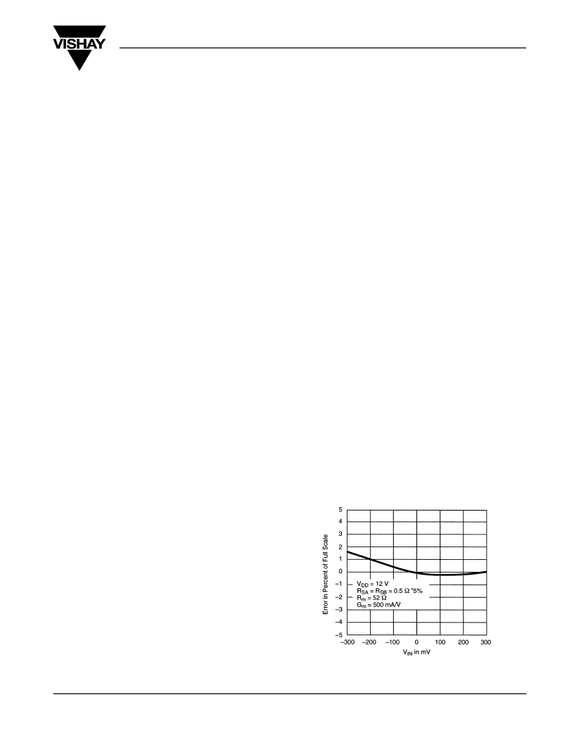
The linearity of the transconductance amplifier (around a
center value of 500 mA/volt) is shown in Figure 2. In this case,
the output current sense resistors (R
SA
and R
SB
) were ±5%
tolerance, 0.5
. Any mismatch between R
SA
and R
SB
contribute directly to mismatch between the positive and
negative “full-scale”. Including the external resistor mismatch,
the overall loop nonlinearity is approximately 1% maximum
over a ±250-mV input voltage range.
FIGURE 2.
Si9961 Transconductance End Point
Non-Linearity
f
s
50
440
60
÷
(
)
×
=
This is a sample frequency of 3667 H
f
3db
367
tan 10
)
(
)
÷
=
A
s
p
+
(
)
s
x
+
(
)
÷
(
)
×
=
V
O
A
---+
)
e
×
=
V
O
p
L
v
×
(
)
B
÷
=
Att
0
相關(guān)PDF資料 |
PDF描述 |
|---|---|
| Si9976DY | N-Channel Half-Bridge Driver(N溝道半橋驅(qū)動器) |
| Si9978DW | Configurable H-Bridge Driver(可配置的H橋驅(qū)動器) |
| Si9979 | 3-Phase Brushless DC Motor Controller(3相位無電刷直流電機驅(qū)動器) |
| Si9986 | Buffered H-Bridge(兼容TTL輸入的1.0A緩沖H橋) |
| SiP2213DLP-AA-T1 | Cap-Free, NMOS, 150mA Low Dropout Regulator with Reverse Current Protection |
相關(guān)代理商/技術(shù)參數(shù) |
參數(shù)描述 |
|---|---|
| SI9961A | 制造商:VISHAY 制造商全稱:Vishay Siliconix 功能描述:12-V Voice Coil Motor Driver |
| SI9961ACY | 功能描述:馬達/運動/點火控制器和驅(qū)動器 Voice Coil Driver RoHS:否 制造商:STMicroelectronics 產(chǎn)品:Stepper Motor Controllers / Drivers 類型:2 Phase Stepper Motor Driver 工作電源電壓:8 V to 45 V 電源電流:0.5 mA 工作溫度:- 25 C to + 125 C 安裝風格:SMD/SMT 封裝 / 箱體:HTSSOP-28 封裝:Tube |
| SI9961ACY-E3 | 功能描述:馬達/運動/點火控制器和驅(qū)動器 Voice Coil Driver RoHS:否 制造商:STMicroelectronics 產(chǎn)品:Stepper Motor Controllers / Drivers 類型:2 Phase Stepper Motor Driver 工作電源電壓:8 V to 45 V 電源電流:0.5 mA 工作溫度:- 25 C to + 125 C 安裝風格:SMD/SMT 封裝 / 箱體:HTSSOP-28 封裝:Tube |
| SI9961ACY-T1 | 功能描述:馬達/運動/點火控制器和驅(qū)動器 Voice Coil Driver RoHS:否 制造商:STMicroelectronics 產(chǎn)品:Stepper Motor Controllers / Drivers 類型:2 Phase Stepper Motor Driver 工作電源電壓:8 V to 45 V 電源電流:0.5 mA 工作溫度:- 25 C to + 125 C 安裝風格:SMD/SMT 封裝 / 箱體:HTSSOP-28 封裝:Tube |
| SI9961ACY-T1-E3 | 功能描述:馬達/運動/點火控制器和驅(qū)動器 Voice Coil Driver RoHS:否 制造商:STMicroelectronics 產(chǎn)品:Stepper Motor Controllers / Drivers 類型:2 Phase Stepper Motor Driver 工作電源電壓:8 V to 45 V 電源電流:0.5 mA 工作溫度:- 25 C to + 125 C 安裝風格:SMD/SMT 封裝 / 箱體:HTSSOP-28 封裝:Tube |
發(fā)布緊急采購,3分鐘左右您將得到回復(fù)。