- 您現(xiàn)在的位置:買(mǎi)賣(mài)IC網(wǎng) > PDF目錄31155 > SMBJ5.0 (GENERAL SEMICONDUCTOR INC) 600 W, UNIDIRECTIONAL, SILICON, TVS DIODE, DO-214AA PDF資料下載
參數(shù)資料
| 型號(hào): | SMBJ5.0 |
| 廠(chǎng)商: | GENERAL SEMICONDUCTOR INC |
| 元件分類(lèi): | TVS二極管 - 瞬態(tài)電壓抑制 |
| 英文描述: | 600 W, UNIDIRECTIONAL, SILICON, TVS DIODE, DO-214AA |
| 封裝: | PLASTIC, SMB, 2 PIN |
| 文件頁(yè)數(shù): | 1/4頁(yè) |
| 文件大小: | 75K |
| 代理商: | SMBJ5.0 |
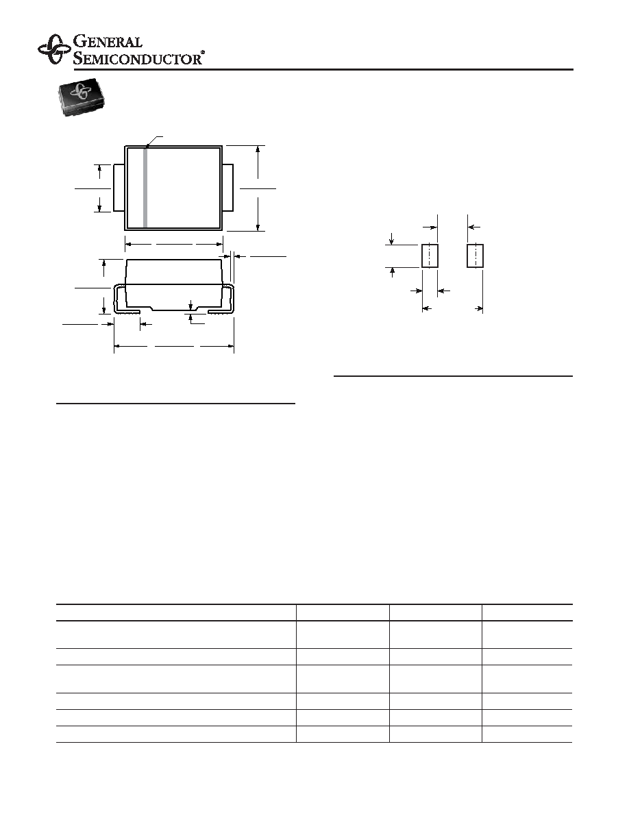
0.180 (4.57)
0.160 (4.06)
0.012 (0.305)
0.006 (0.152)
0.008
(0.203)
Max.
0.220 (5.59)
0.205 (5.21)
0.060 (1.52)
0.030 (0.76)
0.155 (3.94)
0.130 (3.30)
0.086 (2.20)
0.077 (1.95)
0.096 (2.44)
0.084 (2.13)
Cathode Band
SMBJ5.0 thru 188CA
Surface Mount TRANSZORB
Transient Voltage Suppressors
Stand-off Voltage 5.0 to 188V
Peak Pulse Power 600W
Dimensions in inches
and (millimeters)
DO-214AA (SMB J-Bend)
Features
Plastic package has Underwriters Laboratory
Flammability Classification 94V-0
Low profile package with built-in strain relief for surface
mounted applications
Glass passivated junction
Low incremental surge resistance, excellent clamping
capability
600W peak pulse power capability with a 10/1000
s
waveform, repetition rate (duty cycle): 0.01%
Very fast response time
High temperature soldering guaranteed:
250°C/10 seconds at terminals
Contact local sales office for gull-wing (SMBG prefix)
lead form (DO-215AA)
Mechanical Data
Case: JEDEC DO-214AA molded plastic over
passivated junction
Terminals: Solder plated, solderable per
MIL-STD-750, Method 2026
Polarity: For unidirectional types the band denotes the
cathode, which is positive with respect to the anode
under normal TVS operation
Weight: 0.003oz., 0.093g
Packaging Codes – Options (Antistatic):
51 – 2K per Bulk box, 20K/carton
52 – 750 per 7” plastic Reel (12mm tape), 15K/carton
5B – 3.2K per 13” plastic Reel (12mm tape), 32K/carton
0.106 MAX
(2.69 MAX)
0.050 MIN
(1.27 MIN)
0.220 REF
0.083 MIN
(2.10 MIN)
Mounting Pad Layout
Extended
Voltage
Range
Devices for Bidirectional Applications
For bi-directional devices, use suffix C or CA (e.g. SMBJ10C, SMBJ10CA). Electrical characteristics apply in both directions.
.
Maximum Ratings & Thermal Characteristics Ratings at 25°C ambient temperature unless otherwise specified.
Parameter
Symbol
Value
Unit
Peak pulse power dissipation with
PPPM
Minimum 600
W
a 10/1000
s waveform(1)(2) (Fig. 1)
Peak pulse current with a 10/1000
s waveform(1)
IPPM
See Table Below
A
Peak forward surge current 8.3ms single half sine-wave
IFSM
100
A
uni-directional only(2)
Typical thermal resistance, junction to ambient(4)
R
θJA
100
°C/W
Typical thermal resistance, junction to lead
R
θJL
20
°C/W
Operating junction and storage temperature range
TJ, TSTG
–55 to +150
°C
Notes: (1) Non-repetitive current pulse, per Fig.3 and derated above TA = 25°C per Fig. 2
(2) Mounted on 0.2 x 0.2” (5.0 x 5.0mm) copper pads to each terminal
(3) Mounted on minimum recommended pad layout
10/17/01
相關(guān)PDF資料 |
PDF描述 |
|---|---|
| SMBJ64A | 600 W, UNIDIRECTIONAL, SILICON, TVS DIODE, DO-214AA |
| SMBJ13CA-5B | 600 W, BIDIRECTIONAL, SILICON, TVS DIODE, DO-214AA |
| SMBJ15C-5B | 600 W, BIDIRECTIONAL, SILICON, TVS DIODE, DO-214AA |
| SMBJ17C-52 | 600 W, BIDIRECTIONAL, SILICON, TVS DIODE, DO-214AA |
| SMBJ18A-51 | 600 W, UNIDIRECTIONAL, SILICON, TVS DIODE, DO-214AA |
相關(guān)代理商/技術(shù)參數(shù) |
參數(shù)描述 |
|---|---|
| SMBJ50A | 制造商:GENERAL 功能描述:* 制造商:Littelfuse 功能描述: 制造商:Vishay Semiconductors 功能描述: |
| SMBJ50A42LF | 制造商:GEN SEMI 功能描述:Pb Free |
| SMBJ50AE352 | 制造商:Vishay Intertechnologies 功能描述: |
| SMBJ50ATR | 制造商:STMicroelectronics 功能描述: |
| SMBJ50CA | 制造商:Littelfuse 功能描述: |
發(fā)布緊急采購(gòu),3分鐘左右您將得到回復(fù)。