- 您現(xiàn)在的位置:買(mǎi)賣(mài)IC網(wǎng) > PDF目錄373432 > SN54ABT16501A (Texas Instruments, Inc.) 18-Bit Universal Bus Transceivers With 3-State Outputs(18位通用總線收發(fā)器(三態(tài)輸出)) PDF資料下載
參數(shù)資料
| 型號(hào): | SN54ABT16501A |
| 廠商: | Texas Instruments, Inc. |
| 英文描述: | 18-Bit Universal Bus Transceivers With 3-State Outputs(18位通用總線收發(fā)器(三態(tài)輸出)) |
| 中文描述: | 18位通用總線收發(fā)器與三態(tài)輸出(18位通用總線收發(fā)器(三態(tài)輸出)) |
| 文件頁(yè)數(shù): | 4/7頁(yè) |
| 文件大小: | 154K |
| 代理商: | SN54ABT16501A |
SN54ABT16501A, SN74ABT16501A
18-BIT UNIVERSAL BUS TRANSCEIVER
WITH 3-STATE OUTPUTS
SCBS459 – JANUARY 1994
4
POST OFFICE BOX 655303
DALLAS, TEXAS 75265
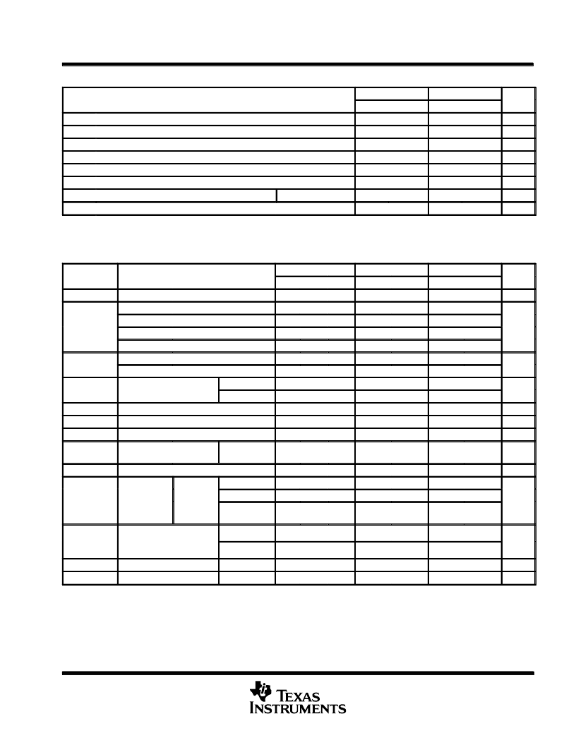
recommended operating conditions (see Note 2)
SN54ABT16501A
MIN
SN74ABT16501A
MIN
UNIT
MAX
MAX
VCC
VIH
VIL
VI
IOH
IOL
t/
v
TA
NOTE 2: Unused or floating pins (input or I/O) must be held high or low.
Supply voltage
4.5
5.5
4.5
5.5
V
High-level input voltage
2
2
V
Low-level input voltage
0.8
0.8
V
Input voltage
0
VCC
–24
0
VCC
–32
V
High-level output current
mA
Low-level output current
48
64
mA
Input transition rise or fall rate
Outputs enabled
10
10
ns/V
°
C
Operating free-air temperature
–55
125
–40
85
electrical characteristics over recommended operating free-air temperature range (unless
otherwise noted)
PARAMETER
TEST CONDITIONS
TA = 25
°
C
TYP
SN54ABT16501A
SN74ABT16501A
UNIT
MIN
MAX
MIN
MAX
MIN
MAX
VIK
VCC = 4.5 V,
VCC = 4.5 V,
VCC = 5 V,
VCC = 4.5 V,
VCC = 4.5 V,
VCC = 4.5 V,
VCC = 4.5 V,
VCC = 5.5 V,
VCC 5.5 V,
VI = VCC or GND
VCC = 5.5 V,
VCC = 5.5 V,
VCC = 0,
II = –18 mA
IOH = – 3 mA
IOH = – 3 mA
IOH = – 24 mA
IOH = – 32 mA
IOL = 48 mA
IOL = 64 mA
–1.2
–1.2
–1.2
V
VOH
2.5
2.5
2.5
V
3
3
3
2
2
2
2
VOL
0.55
0.55
0.55
V
0.55
±
1
±
20
10
II
Control inputs
±
1
±
1
μ
A
A or B ports
±
20
10
±
20
10
IOZH§
IOZL§
Ioff
VO = 2.7 V
VO = 0.5 V
VI or VO
≤
4.5 V
μ
A
μ
A
μ
A
–10
±
100
–10
–10
±
100
ICEX
VCC = 5.5 V,
VO = 5.5 V
Outputs
high
50
50
50
μ
A
IO
VCC = 5.5 V,
VO = 2.5 V
–50
–100
–180
–50
–180
–50
–180
mA
ICC
VCC = 5.5 V,
IO
VI = VCC or
GND
A or B
ports
Outputs high
3
5
3
Outputs low
36
36
36
mA
Outputs
disabled
3
5.3
3
VCC = 5.5 V,
One input at 3 4 V
One input at 3.4 V,
Other inputs at VCC or GND
VI = 2.5 V or 0.5 V
VO = 2.5 V or 0.5 V
Control inputs
50
50
50
μ
A
ICC#
A or B ports
50
50
50
Ci
Cio
Control inputs
3
pF
A or B ports
9
pF
All typical values are at VCC = 5 V.
On products compliant to MIL-STD-883, Class B, this parameter does not apply.
§The parameters IOZH and IOZL include the input leakage current.
Not more than one output should be tested at a time, and the duration of the test should not exceed one second.
#This is the increase in supply current for each input that is at the specified TTL voltage level rather than VCC or GND.
P
發(fā)布緊急采購(gòu),3分鐘左右您將得到回復(fù)。