- 您現(xiàn)在的位置:買賣IC網(wǎng) > PDF目錄202096 > SN54ABT32318PN (TEXAS INSTRUMENTS INC) ABT SERIES, 18-BIT EXCHANGER, TRUE OUTPUT PDF資料下載
參數(shù)資料
| 型號: | SN54ABT32318PN |
| 廠商: | TEXAS INSTRUMENTS INC |
| 元件分類: | 總線收發(fā)器 |
| 英文描述: | ABT SERIES, 18-BIT EXCHANGER, TRUE OUTPUT |
| 文件頁數(shù): | 5/9頁 |
| 文件大小: | 152K |
| 代理商: | SN54ABT32318PN |
SN54ABT32318, SN74ABT32318
18BIT TRIPORT UNIVERSAL BUS EXCHANGERS
SCBS180A JUNE 1992 REVISED JULY 1994
55
POST OFFICE BOX 655303
DALLAS, TEXAS 75265
POST OFFICE BOX 1443
HOUSTON, TEXAS 772511443
absolute maximum ratings over operating free-air temperature range (unless otherwise noted)
Supply voltage range, VCC
0.5 V to 7 V
. . . . . . . . . . . . . . . . . . . . . . . . . . . . . . . . . . . . . . . . . . . . . . . . . . . . . . . . . .
Input voltage range, VI (except I/O ports) (see Note 1)
0.5 V to 7 V
. . . . . . . . . . . . . . . . . . . . . . . . . . . . . . . . . .
Voltage range applied to any output in the high state or power-off state, VO
0.5 V to 5.5 V
. . . . . . . . . . . . .
Current into any output in the low state, IO: SN54ABT32318
96 mA
. . . . . . . . . . . . . . . . . . . . . . . . . . . . . . . . . .
SN74ABT32318
128 mA
. . . . . . . . . . . . . . . . . . . . . . . . . . . . . . . . .
Input clamp current, IIK (VI < 0)
18 mA
. . . . . . . . . . . . . . . . . . . . . . . . . . . . . . . . . . . . . . . . . . . . . . . . . . . . . . . . . . .
Output clamp current, IOK (VO < 0)
50 mA
. . . . . . . . . . . . . . . . . . . . . . . . . . . . . . . . . . . . . . . . . . . . . . . . . . . . . . . .
Maximum power dissipation at TA = 55°C (in still air) (see Note 2)
1.1 W
. . . . . . . . . . . . . . . . . . . . . . . . . . . . . .
Storage temperature range
65
°C to 150°C
. . . . . . . . . . . . . . . . . . . . . . . . . . . . . . . . . . . . . . . . . . . . . . . . . . . . . . . .
Stresses beyond those listed under “absolute maximum ratings” may cause permanent damage to the device. These are stress ratings only, and
functional operation of the device at these or any other conditions beyond those indicated under “recommended operating conditions” is not
implied. Exposure to absolute-maximum-rated conditions for extended periods may affect device reliability.
NOTES:
1. The input and output negative-voltage ratings may be exceeded if the input and output clamp-current ratings are observed.
2. The maximum package power dissipation is calculated using a junction temperature of 150
°C and a board trace length of 75 mils.
For more information, refer to the Package Thermal Considerations application note in the 1994 ABT Advanced BiCMOS Technology
Data Book, literature number SCBD002B.
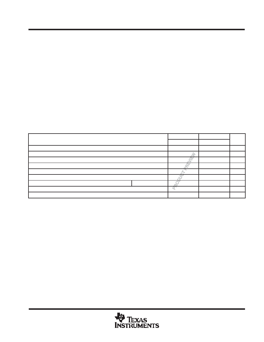
recommended operating conditions (see Note 3)
SN54ABT32318
SN74ABT32318
UNIT
MIN
MAX
MIN
MAX
UNIT
VCC
Supply voltage
4.5
5.5
4.5
5.5
V
VIH
High-level input voltage
2
V
VIL
Low-level input voltage
0.8
V
VI
Input voltage
0
VCC
0
VCC
V
IOH
High-level output current
24
32
mA
IOL
Low-level output current
48
64
mA
t/v
Input transition rise or fall rate
Outputs enabled
10
ns / V
t/VCC Power-up ramp rate
200
s/V
TA
Operating free-air temperature
55
125
40
85
°C
NOTE 3: Unused or floating control pins must be held high or low.
PRODUCT PREVIEW information concerns products in the formative or
design phase of development. Characteristic data and other
specifications are design goals. Texas Instruments reserves the right to
change or discontinue these products without notice.
相關(guān)PDF資料 |
PDF描述 |
|---|---|
| SN74HC258PWRE4 | HC/UH SERIES, QUAD 2 LINE TO 1 LINE MULTIPLEXER, INVERTED OUTPUT, PDSO16 |
| SN74ABT373PWRE4 | ABT SERIES, 8-BIT DRIVER, TRUE OUTPUT, PDSO20 |
| SN74ALS153DE4 | ALS SERIES, DUAL 4 LINE TO 1 LINE MULTIPLEXER, TRUE OUTPUT, PDSO16 |
| SN54LS191JD | LS SERIES, SYN POSITIVE EDGE TRIGGERED 4-BIT BIDIRECTIONAL BINARY COUNTER, CDIP16 |
| SN74CBT3384CDBQRE4 | CBT/FST/QS/5C/B SERIES, 10-BIT DRIVER, TRUE OUTPUT, PDSO24 |
相關(guān)代理商/技術(shù)參數(shù) |
參數(shù)描述 |
|---|---|
| SN54ABT32501 | 制造商:TI 制造商全稱:Texas Instruments 功能描述:36-BIT UNIVERSAL BUS TRANSCEIVERS WITH 3-STATE OUTPUTS |
| SN54ABT32543 | 制造商:TI 制造商全稱:Texas Instruments 功能描述:36-BIT REGISTERED BUS TRANSCEIVERS WITH 3-STATE OUTPUTS |
| SN54ABT3614 | 制造商:TI 制造商全稱:Texas Instruments 功能描述:64 】 36 】 2 CLOCKED BIDIRECTIONAL FIRST-IN, FIRST-OUT MEMORY WITH BUS MATCHING AND BYTE SWAPPING |
| SN54ABT3614HFP | 制造商:Texas Instruments 功能描述:FIFO SYNC DUAL BI-DIR 64 X 36 X 2 132CFPAK - Bulk |
| SN54ABT3614PCB | 制造商:TI 制造商全稱:Texas Instruments 功能描述:64 】 36 】 2 CLOCKED BIDIRECTIONAL FIRST-IN, FIRST-OUT MEMORY WITH BUS MATCHING AND BYTE SWAPPING |
發(fā)布緊急采購,3分鐘左右您將得到回復(fù)。