- 您現(xiàn)在的位置:買賣IC網(wǎng) > PDF目錄372179 > SP3281EBEA 5V High-Speed RS-232 Transceivers with 0.1uF Capacitors PDF資料下載
參數(shù)資料
| 型號: | SP3281EBEA |
| 元件分類: | RS-232 |
| 英文描述: | 5V High-Speed RS-232 Transceivers with 0.1uF Capacitors |
| 中文描述: | 5V的高速RS - 232收發(fā)器與0.1uF電容 |
| 文件頁數(shù): | 1/3頁 |
| 文件大?。?/td> | 41K |
| 代理商: | SP3281EBEA |

Si9717
Vishay Siliconix
Document Number: 70023
S-40743—Rev. D, 19-Apr-04
www.vishay.com
1
Battery Disconnect Switch
FEATURES
6- to 18-V Operation
Separate Logic Voltage Input
Undervoltage Lockout (UVL) @ V
L
= 3 V
Shutdown Control Capability
Safe Power Down
DESCRIPTION
The is a reverse blocking switch for battery disconnect
applications. It is an integrated solution for multiple battery
technology designs or designs that require isolation from the
power bus during charging. The is available in a 16-pin SOIC
package and is rated for the commercial temperature range of
0 to 70 C.
The Si9717 is available in both standard and lead (Pb)-free
packages.
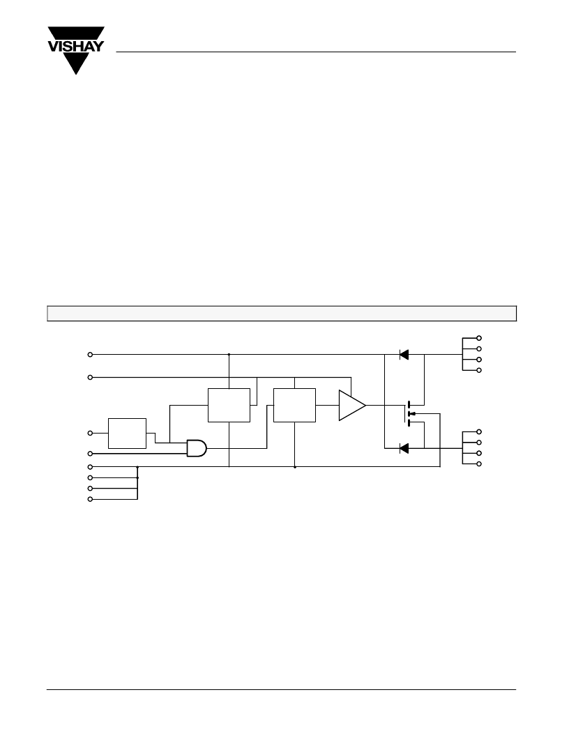
FUNCTIONAL BLOCK DIAGRAM
Level
Shift
Charge
Pump
CBP
CP
ENABLE
GND
A
B
IN
Under
Voltage
Detect
7
10
6
11
1
8
9
16
3
4
5
2
13
14
15
12
ABSOLUTE MAXIMUM RATINGS
Voltage Referenced to GND
V
A
, V
B
. . . . . . . . . . . . . . . . . . . . . . . . . . . . . . . . . . . . . . . . . . . . . . .
V
IN
. . . . . . . . . . . . . . . . . . . . . . . . . . . . . . . . . . . . . . . . . . . . . . . . . .
V
ENABLE
. . . . . . . . . . . . . . . . . . . . . . . . . . . . . . . . . . . . . . . . . . . . . .
0.3 to 20 V
0.3 to 10 V
0.3 to 10 V
Storage Temperature
Power Dissipation
65 to 125 C
. . . . . . . . . . . . . . . . . . . . . . . . . . . . . . . . . .
. . . . . . . . . . . . . . . . . . . . . . . . . . . . . . . . . . . . . . . . . . . . .
2 W
Notes: Device mounted with all leads soldered to PC board.
RECOMMENDED OPERATING RANGE
V
A
, V
B
(see note)
V
IN
. . . . . . . . . . . . . . . . . . . . . . . . . . . . . . . . . . . . . . . . . . . . . . . . . . . . . .
I
AB
(continuous)
. . . . . . . . . . . . . . . . . . . . . . . . . . . . . . . . . . . . . . . . . . .
I
AB
x V
A
(continuous)
. . . . . . . . . . . . . . . . . . . . . . . . . . . . . . . . . . . . .
Minimum Cycle Time (turn-on to turn-on)
V
ENABLE
. . . . . . . . . . . . . . . . . . . . . . . . . . . . . . . . . . . . . . . . . . . . . . . . . .
6 to 18 V
0 to 5 V
0 to 4 A
0 to 40 W
10 ms
0 to 5 V
. . . . . . . . . . . . . . . . . . . . . . . . . . . . . . . . . . . . . . . . .
. . . . . . . . . . . . . . . . . . . . . . .
Operating Temperature
Junction Temperature
0 to 70 C
0 to 150 C
. . . . . . . . . . . . . . . . . . . . . . . . . . . . . . . . . . .
. . . . . . . . . . . . . . . . . . . . . . . . . . . . . . . . . . .
Notes:
a.
is functional at V
A
, V
B
= 5 to 6 V with higher supply current. See I
A(on)
specification.
相關(guān)PDF資料 |
PDF描述 |
|---|---|
| SP3281EBEY | 5V High-Speed RS-232 Transceivers with 0.1uF Capacitors |
| SP3282EBCA | 5V High-Speed RS-232 Transceivers with 0.1uF Capacitors |
| SP3282 | Replaced by ADS7842 : |
| SP3282EB | Replaced by ADS7842 : |
| SP3282EBCY | 5V High-Speed RS-232 Transceivers with 0.1uF Capacitors |
相關(guān)代理商/技術(shù)參數(shù) |
參數(shù)描述 |
|---|---|
| SP3281EBEY | 制造商:SIPEX 制造商全稱:Sipex Corporation 功能描述:Intelligent +2.35V to +5.5V RS-232 Transceivers |
| SP3282 | 制造商:SIPEX 制造商全稱:Sipex Corporation 功能描述:Intelligent +2.35V to +5.5V RS-232 Transceivers |
| SP3282EB | 制造商:SIPEX 制造商全稱:Sipex Corporation 功能描述:Intelligent +2.35V to +5.5V RS-232 Transceivers |
| SP3282EBCA | 制造商:SIPEX 制造商全稱:Sipex Corporation 功能描述:Intelligent +2.35V to +5.5V RS-232 Transceivers |
| SP3282EBCA/TR | 制造商:SIPEX 制造商全稱:Sipex Corporation 功能描述:Intelligent +2.35V to +5.5V RS-232 Transceivers |
發(fā)布緊急采購,3分鐘左右您將得到回復(fù)。