- 您現(xiàn)在的位置:買賣IC網(wǎng) > PDF目錄372200 > SP8538JN RECTIFIER STANDARD SINGLE 1A 50V 50 30A-ifsm 5uA-ir 1.1V-vf MELF 5K/REEL PDF資料下載
參數(shù)資料
| 型號: | SP8538JN |
| 英文描述: | RECTIFIER STANDARD SINGLE 1A 50V 50 30A-ifsm 5uA-ir 1.1V-vf MELF 5K/REEL |
| 中文描述: | 微采樣12位A / D轉(zhuǎn)換器 |
| 文件頁數(shù): | 2/12頁 |
| 文件大小: | 305K |
| 代理商: | SP8538JN |

SP8538DS/01
SP8538 Micropower Sampling 12-Bit A/D Converter
2
Copyright 1999 Sipex Corporation
ABSOLUTE MAXIMUM RATINGS
These are stress ratings only and functional operation of the device at
these ratings or any other above those indicated in the operation
sections of the specifications below is not implied. Exposure to absolute
maximum rating conditions for extended periods of time may affect
reliability.
(TA=+25C unless otherwise noted) .....................................................
VCC to GND ................................................................................. 7.0V
Vin to GND .............................................................. -0.3 to VCC +0.3V
Digital input to GND ................................................ -0.3 to VCC +0.3V
Digital output to GND .............................................. -0.3 to VCC +0.3V
Operating Temperature Range
Commercial (J, K Version) ........................................... 0C to 70C
Industrial (A, B Version) .......................................... -40C to +85C
Lead Temperature (Solder 10Sec) ............................................ +300C
Storage Temperature .................................................. -65C to +150C
Power Dissipation to 70C ........................................................ 500mW
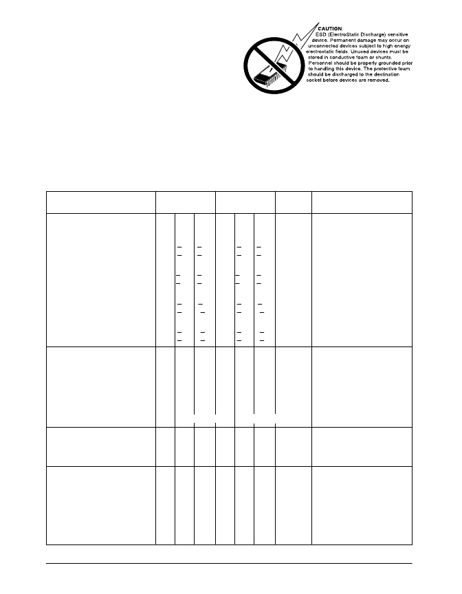
SPECIFICATIONS
Unless otherwise noted the following specifications apply for VCC=5V or 3.3V with limits applicable for Tmin to Tmax. Typical applies for Ta=25C.
VCC=5.0V
PARAMETERS
MIN. TYP. MAX. MIN. TYP. MAX.
DC ACCURACY
Resolution
12
Integral Linearity
J,A
+0.6 +2.0
K,B
+0.6 +1.0
Differential Linearity Error
J,A
+0.75 +2.0
K,B
+0.75 +1.0
Gain Error
J,A
+2.0 +10
K,B
+2.0
Offset Error
J,A
+1.5
K,B
+1.5
VCC=3.3V
UNITS
CONDITIONS
12
Bits
+0.6 +2.0
+0.6 +1.0
LSB
LSB
+0.75 +2.0
+0.75 +1.0
LSB
LSB
No Missing Codes
+2.0 +10
+2.0
LSB
LSB
+8
+8
+5
+3
+3.0
+3.0
+8
+5
LSB
LSB
ANALOG INPUT
Input Signal FS Range
Input Impedance
On Channel
0
V
CC
0
V
CC
20
100
3
100
.001
20
100
3
100
.001
pF
M
pF
M
μ
A
Volts
In Parallel with 100m
Off Channel
In Parallel with 100m
Input Bias Current
Analog Input Range
1
1
-.05
V
CC
+.05 -.05
V
CC
+.05
MULTIPLEXER
Crosstalk (f
= Nyquist)
Feedthrough (f
D
= Nyquist)
-90
-90
-90
-90
dB
dB
Off to On Channel
Off to On Channel
f
D
= Disturbance
CONVERSION SPEED
Sample Time
1.5
1.5
clock
cycles
clock
cycles
kHz
μ
S
μ
S
μ
S
See Timing Diagrams
Conversion Time
12
12
See Timing Diagrams
Complete Cycle
Clock Period
Clock High Time
Clock Low Time
25
5.85
See Timing Diagrams
See Timing Diagrams
See Timing Diagrams
See Timing Diagrams
2.25
1.0
1.0
10.0
4.5
4.5
相關(guān)PDF資料 |
PDF描述 |
|---|---|
| SP8538 | Micropower Sampling 12-Bit A/D Converter |
| SP8538AN | Micropower Sampling 12-Bit A/D Converter |
| SP8538AS | Micropower Sampling 12-Bit A/D Converter |
| SP8538BN | Micropower Sampling 12-Bit A/D Converter |
| SP8538BS | Micropower Sampling 12-Bit A/D Converter |
相關(guān)代理商/技術(shù)參數(shù) |
參數(shù)描述 |
|---|---|
| SP8538JS | 制造商:SIPEX 制造商全稱:Sipex Corporation 功能描述:Micropower Sampling 12-Bit A/D Converter |
| SP8538KN | 制造商:SIPEX 制造商全稱:Sipex Corporation 功能描述:Micropower Sampling 12-Bit A/D Converter |
| SP8538KS | 制造商:SIPEX 制造商全稱:Sipex Corporation 功能描述:Micropower Sampling 12-Bit A/D Converter |
| SP8542 | 制造商:SIPEX 制造商全稱:Sipex Corporation 功能描述:Two and Four Channel 12-Bit Multiplexed Sampling ADCs |
| SP8542AN | 制造商:SIPEX 制造商全稱:Sipex Corporation 功能描述:Two and Four Channel 12-Bit Multiplexed Sampling ADCs |
發(fā)布緊急采購,3分鐘左右您將得到回復。