- 您現(xiàn)在的位置:買賣IC網(wǎng) > PDF目錄231018 > ST180C16C1L (VISHAY SEMICONDUCTORS) 660 A, 1600 V, SCR, TO-200AB PDF資料下載
參數(shù)資料
| 型號(hào): | ST180C16C1L |
| 廠商: | VISHAY SEMICONDUCTORS |
| 元件分類: | 晶閘管 |
| 英文描述: | 660 A, 1600 V, SCR, TO-200AB |
| 封裝: | APUK-2 |
| 文件頁(yè)數(shù): | 6/7頁(yè) |
| 文件大小: | 87K |
| 代理商: | ST180C16C1L |
ST180C..C Series
6
www.irf.com
Bulletin I25164 rev. C 02/00
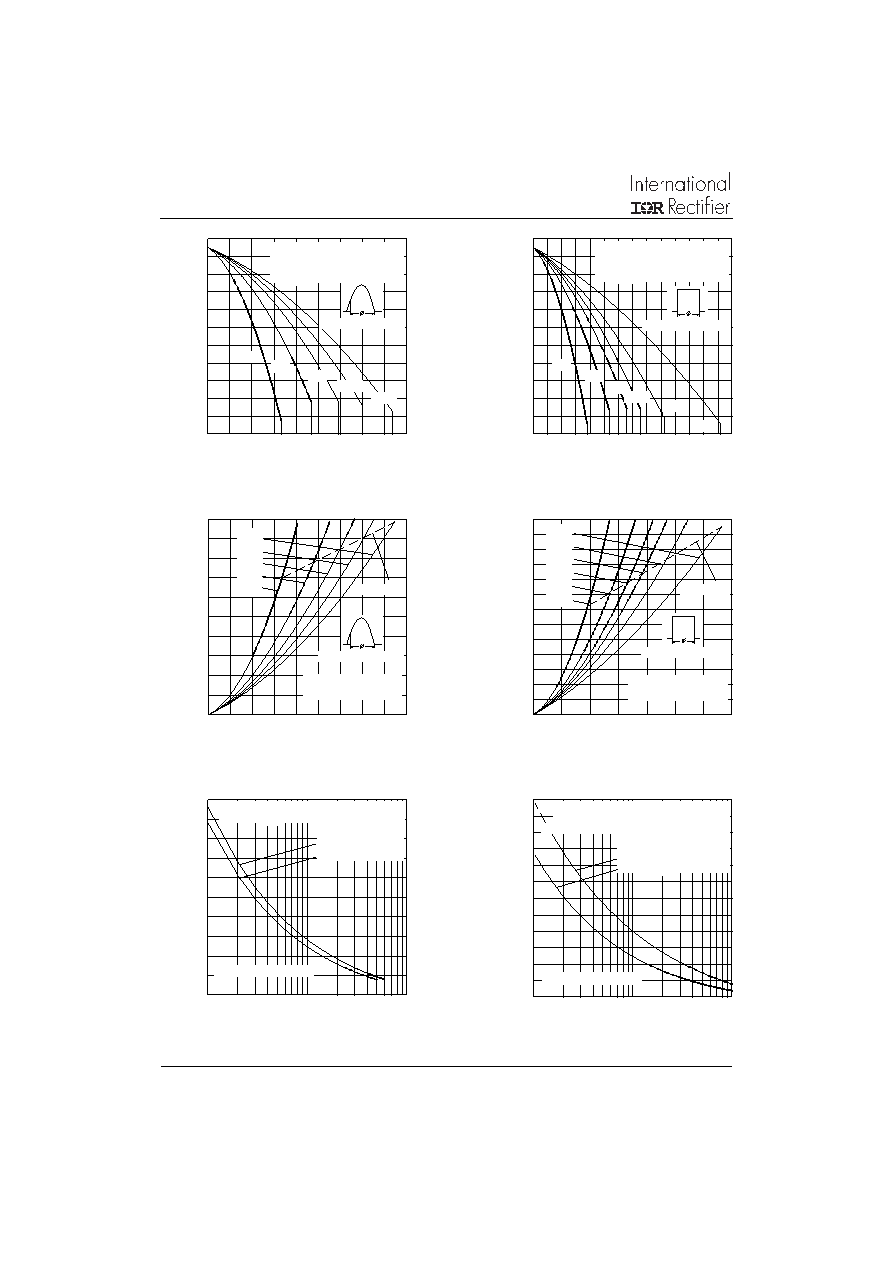
Fig. 7 - Maximum Non-Repetitive Surge Current
Single and Double Side Cooled
Fig. 3 - Current Ratings Characteristics
Fig. 4 - Current Ratings Characteristics
Fig. 5- On-state Power Loss Characteristics
Fig. 6- On-state Power Loss Characteristics
Fig. 8 - Maximum Non-Repetitive Surge Current
Single and Double Side Cooled
Average On-state Current (A)
Maximum
Allowable
Heatsink
Temperature
(
°C)
Average On-state Current (A)
Maximum
Average
On-state
Power
Loss
(W)
Average On-state Current (A)
Maximum
Average
On-state
Power
Loss
(W)
Number Of Equal Amplitude Half Cycle Current Pulses (N)
Peak
Half
Sine
Wave
On-state
Current
(A)
Pulse Train Duration (s)
Peak
Half
Sine
Wave
On-state
Current
(A)
Maximum
Allowable
Heatsink
Temperature
(
°C)
20
30
40
50
60
70
80
90
100
110
120
130
0
50 100 150 200 250 300 350 400 450
30
60
90
120
180
Conduction Angle
ST180C..C Series
(Double Side Cooled)
R
(DC) = 0.08 K/W
thJ-hs
20
30
40
50
60
70
80
90
100
110
120
130
0
100 200 300 400 500 600 700
DC
30
60
90
120
180
Conduction Period
ST180C..C Series
(Double Side Cooled)
R
(DC) = 0.08 K/W
thJ-hs
0
100
200
300
400
500
600
700
800
900
1000
0
50 100 150 200 250 300 350 400 450
180
120
90
60
30
RMS Limit
Conduction Angle
ST180C..C Series
T = 125C
J
0
100
200
300
400
500
600
700
800
900
1000
1100
1200
1300
0
100 200 300 400 500 600 700
DC
180
120
90
60
30
RMS Limit
Conduction Period
ST180C..C Series
T = 125C
J
2000
2500
3000
3500
4000
4500
1
10
100
Initial T = 125C
@ 60 Hz 0.0083 s
@ 50 Hz 0.0100 s
J
ST180C..C Series
At Any Rated Load Condition And With
Rated V
Applied Following Surge.
RRM
2000
2500
3000
3500
4000
4500
5000
0.01
0.1
1
Versus Pulse Train Duration. Control
Of Conduction May Not Be Maintained.
ST180C..C Series
Maximum Non Repetitive Surge Current
Initial T = 125C
No Voltage Reapplied
Rated V
Reapplied
RRM
J
相關(guān)PDF資料 |
PDF描述 |
|---|---|
| ST180C16C1 | 660 A, 1600 V, SCR, TO-200AB |
| ST180C18C0 | 660 A, 1800 V, SCR, TO-200AB |
| ST1230C08K1 | 3200 A, 800 V, SCR |
| ST1230C12K0L | 3200 A, 1200 V, SCR |
| ST1230C12K0 | 3200 A, 1200 V, SCR |
相關(guān)代理商/技術(shù)參數(shù) |
參數(shù)描述 |
|---|---|
| ST180C16C1PBF | 制造商:Vishay Intertechnologies 功能描述: |
| ST180C16C2 | 制造商:IRF 制造商全稱:International Rectifier 功能描述:PHASE CONTROL THYRISTORS |
| ST180C16C2L | 制造商:IRF 制造商全稱:International Rectifier 功能描述:PHASE CONTROL THYRISTORS |
| ST180C16C3 | 制造商:IRF 制造商全稱:International Rectifier 功能描述:PHASE CONTROL THYRISTORS |
| ST180C16C3L | 制造商:IRF 制造商全稱:International Rectifier 功能描述:PHASE CONTROL THYRISTORS |
發(fā)布緊急采購(gòu),3分鐘左右您將得到回復(fù)。