- 您現(xiàn)在的位置:買賣IC網(wǎng) > PDF目錄372302 > ST52F514F0B6 IC MAX 7000 CPLD 128 144-TQFP PDF資料下載
參數(shù)資料
| 型號(hào): | ST52F514F0B6 |
| 英文描述: | IC MAX 7000 CPLD 128 144-TQFP |
| 中文描述: | 微控制器 |
| 文件頁數(shù): | 92/106頁 |
| 文件大小: | 648K |
| 代理商: | ST52F514F0B6 |
第1頁第2頁第3頁第4頁第5頁第6頁第7頁第8頁第9頁第10頁第11頁第12頁第13頁第14頁第15頁第16頁第17頁第18頁第19頁第20頁第21頁第22頁第23頁第24頁第25頁第26頁第27頁第28頁第29頁第30頁第31頁第32頁第33頁第34頁第35頁第36頁第37頁第38頁第39頁第40頁第41頁第42頁第43頁第44頁第45頁第46頁第47頁第48頁第49頁第50頁第51頁第52頁第53頁第54頁第55頁第56頁第57頁第58頁第59頁第60頁第61頁第62頁第63頁第64頁第65頁第66頁第67頁第68頁第69頁第70頁第71頁第72頁第73頁第74頁第75頁第76頁第77頁第78頁第79頁第80頁第81頁第82頁第83頁第84頁第85頁第86頁第87頁第88頁第89頁第90頁第91頁當(dāng)前第92頁第93頁第94頁第95頁第96頁第97頁第98頁第99頁第100頁第101頁第102頁第103頁第104頁第105頁第106頁

ST52F510/F513/F514
92/106
0: Standard I
2
C Mode
1: Fast I
2
C Mode
Bit 6-0:
CC6-CC0
7-bit clock divider
These bits select the speed of the bus (F
SCL
)
depending on the I
2
C mode. They are not
cleared when the interface is disabled
(PE=0).
– Standard mode(FM/SM=0): F
SCL
<=100kHz
F
SCL
= f
CPU
/(3x([CC6..CC0]+9))
– Fast mode (FM/SM=1): F
SCL
> 100kHz
F
SCL
= f
CPU
/(2x([CC6..CC0]+7))
Warning:
For safety reason, CC6-CC0 bits must
be configured with a value >= 3 for the Standard
mode and >=2 for the Fast mode.
I
2
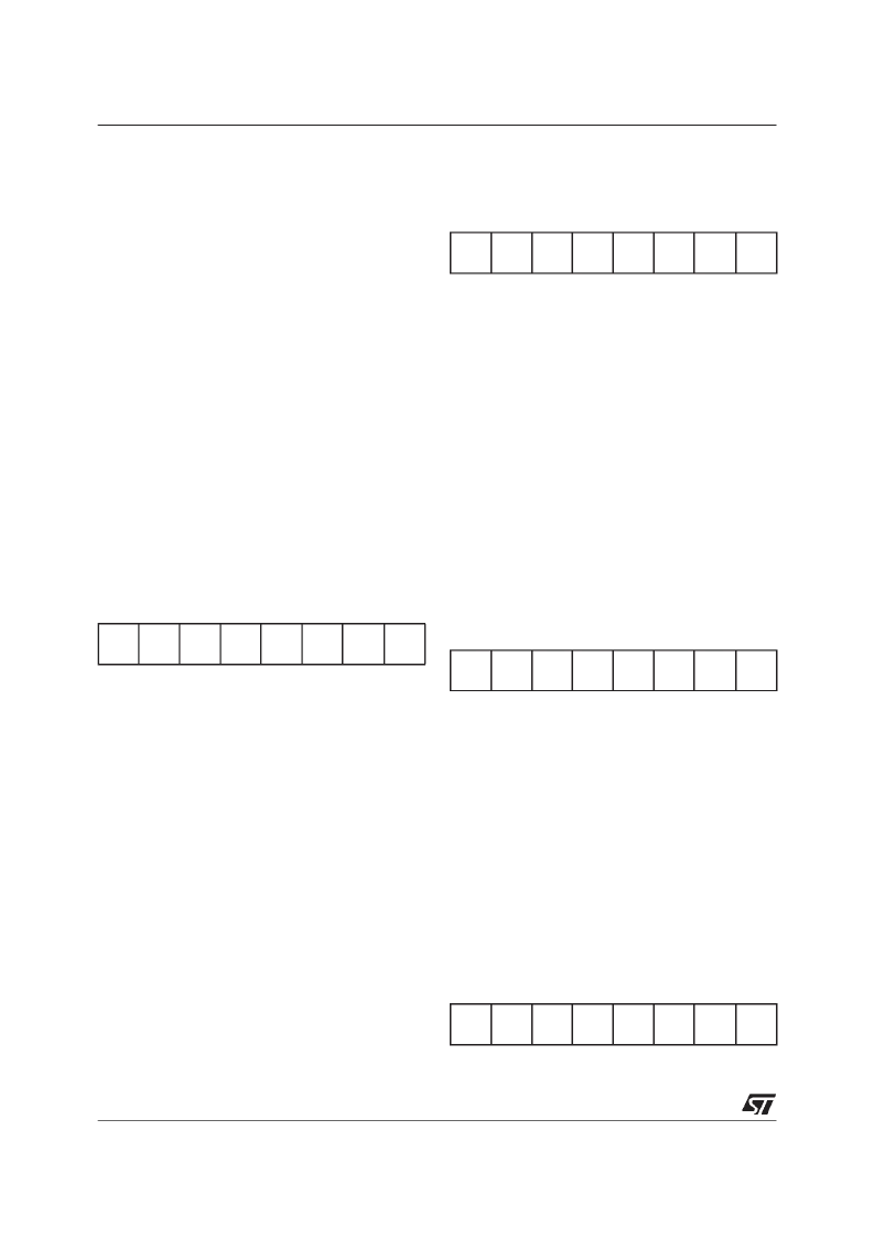
C Own Address Register 1 (I2C_OAR1)
Configuration Register 18 (012h) Read/Write
Reset Value: 0000 0000 (00h)
7-bit Addressing Mode
bit 7-1:
ADD7-ADD1
Interface address.
These bits define the I
2
C bus address of the
interface. They are not cleared when the
interface is disabled (PE=0).
Bit 0:
ADD0
Address direction bit.
This
bit
is
acknowledges either 0 or 1. It is not cleared
when the interface is disabled (PE=0).
“don’t
care”,
the
interface
Note:
Address 01h is always ignored.
10-bit Addressing Mode
bit 7-0:
ADD7-ADD0
Interface address.
These are the least significant bits of the I
2
C
bus address of the interface. They are not
cleared when the interface is disabled
(PE=0).
I
2
C Own Address Register 2 (I2C_OAR2)
Configuration Register 19 (013h) Read/Write
Reset Value: 0000 0000 (00h)
Bit 7-3: Not Used
bit 7-1:
ADD8-ADD8
Interface address.
These are the most significant bits of th I
2
C
bus address of the interface (10-bit mode
only). They are not cleared when the
interface is disabled (PE=0).
Bit 0: Reserved
14.5.2 I
2
C Interface Input Registers.
I
2
C Data Input Register (I2C_IN)
Input Register 6 (06h) Read only
Reset Value: 0000 0000 (00h)
bit 7-0:
I2CDI7-I2CDI0
Received data.
These bits contain the byteto be received from the
bus in Receiver mode: the first data byte is
received automatically in the I2C_IN register using
the least significant bit of the address.
Then, the nextdata bytes are received one by one
after reading the I2C_IN register.
I
2
C Status Register 1 (I2C_SR1)
Input Register 7 (07h) Read only
Reset Value: 0000 0000 (00h)
7
0
ADD7
ADD6
ADD5
ADD4
ADD3
ADD2
ADD1
ADD0
7
2
0
-
-
-
-
-
ADD9
ADD8
-
7
0
I2CDI7
I2CDI6
I2CDI5
I2CDI4
I2CDI3
I2CDI2
I2CDI1
I2CDI0
7
0
EVF
ADD10
TRA
BUSY
BTF
ADSL
M/SL
SB
相關(guān)PDF資料 |
PDF描述 |
|---|---|
| ST52F514F0M6 | IC MAX 7000 CPLD 160 100-TQFP |
| ST52F514F1B6 | IC MAX 7000 CPLD 160 100-TQFP |
| ST52F514F1M6 | IC MAX 7000 CPLD 256 208-PQFP |
| ST52F514F3B6 | IC MAX 7000 CPLD 256 208-PQFP |
| ST52F514F3M6 | IC MAX 7000 CPLD 256 256-FBGA |
相關(guān)代理商/技術(shù)參數(shù) |
參數(shù)描述 |
|---|---|
| ST52F514F0M6 | 制造商:未知廠家 制造商全稱:未知廠家 功能描述:Microcontroller |
| ST52F514F1B6 | 制造商:未知廠家 制造商全稱:未知廠家 功能描述:Microcontroller |
| ST52F514F1M6 | 制造商:未知廠家 制造商全稱:未知廠家 功能描述:Microcontroller |
| ST52F514F3B6 | 制造商:未知廠家 制造商全稱:未知廠家 功能描述:Microcontroller |
| ST52F514F3M6 | 制造商:未知廠家 制造商全稱:未知廠家 功能描述:Microcontroller |
發(fā)布緊急采購(gòu),3分鐘左右您將得到回復(fù)。