- 您現(xiàn)在的位置:買賣IC網(wǎng) > PDF目錄98144 > ST6218CB6/XXX (STMICROELECTRONICS) 8-BIT, MROM, 8 MHz, MICROCONTROLLER, PDIP20 PDF資料下載
參數(shù)資料
| 型號: | ST6218CB6/XXX |
| 廠商: | STMICROELECTRONICS |
| 元件分類: | 微控制器/微處理器 |
| 英文描述: | 8-BIT, MROM, 8 MHz, MICROCONTROLLER, PDIP20 |
| 封裝: | 0.300 INCH, PLASTIC, DIP-20 |
| 文件頁數(shù): | 50/82頁 |
| 文件大?。?/td> | 937K |
| 代理商: | ST6218CB6/XXX |
第1頁第2頁第3頁第4頁第5頁第6頁第7頁第8頁第9頁第10頁第11頁第12頁第13頁第14頁第15頁第16頁第17頁第18頁第19頁第20頁第21頁第22頁第23頁第24頁第25頁第26頁第27頁第28頁第29頁第30頁第31頁第32頁第33頁第34頁第35頁第36頁第37頁第38頁第39頁第40頁第41頁第42頁第43頁第44頁第45頁第46頁第47頁第48頁第49頁當(dāng)前第50頁第51頁第52頁第53頁第54頁第55頁第56頁第57頁第58頁第59頁第60頁第61頁第62頁第63頁第64頁第65頁第66頁第67頁第68頁第69頁第70頁第71頁第72頁第73頁第74頁第75頁第76頁第77頁第78頁第79頁第80頁第81頁第82頁

Obsolete
Product(s)
- Obsolete
Product(s)
54/82
ST62T18C/E18C
U. A. R. T (Cont’d)
4.5.2 Clock Generation
The UART contains a built-in divider of the MCU
internal clock for most common Baud Rates as
shown in Table 19. Other baud rate values can be
calculated from the chosen oscillator frequency di-
vided by the Divisor value shown.
The divided clock provides a frequency that is 8
times the desired baud rate. This allows the Data
reception mechanism to provide a 2 to 1 majority
voting system to determine the logic state of the
asynchronous incoming serial logic bit by taking 3
timed samples within the 8 time states.
The bits not sampled provide a buffer to compen-
sate for frequency offsets between sender and re-
ceiver.
4.5.3 Data Transmission
Whatever the format selected as MCU option, 10-
bit or 11-bit frame, the start and stop bit are auto-
matically generated by the UART. Only the re-
maining 8 (Resp. 9) bit in the 10-bit (Resp. 11-bit)
frame are under control of the user.
Transmission is started by writing the Data Regis-
ter, after having previously set the transmission
software options, the baudrate and the parity ena-
ble. In case of 11-bit frame, the 9th bit must then
be set before into the LSB of the UART Control
Register. Bit 9 remains in the state programmed
for consecutive transmissions until changed by the
user or until a character is received when the state
of this bit is changed to that of the incoming bit 9.
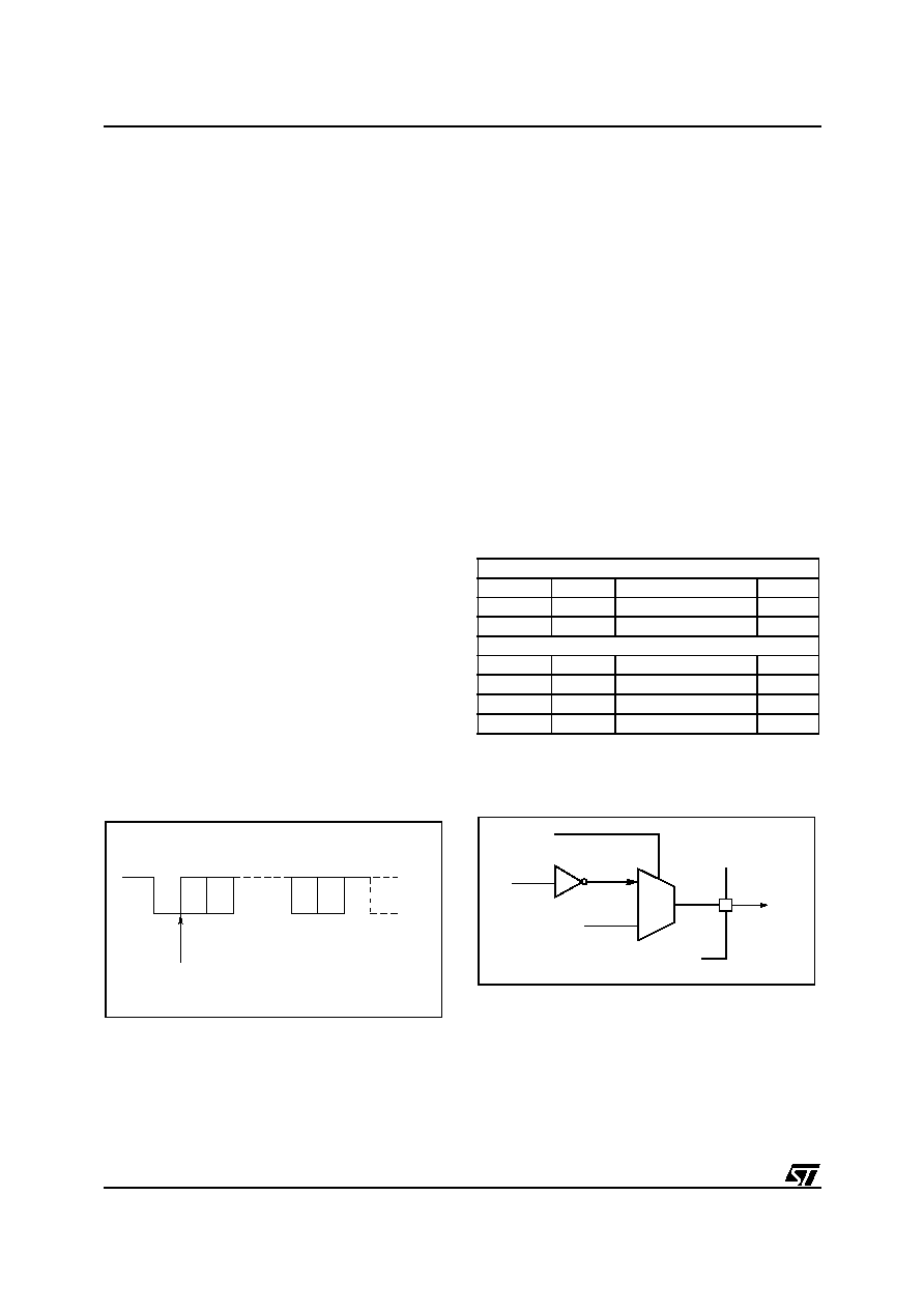
The UARTOE signal switches the output multi-
plexer to the UART output and a start bit is sent (a
0 for one bit time) followed by the data bit with the
LSB D0 at first.. The output is then set to 1 for a
period of one bit time to generate a Stop bit, and
then the UARTOE signal returns the TXD1 line to
its alternate I/O function. The end of transmission
is flagged by setting TXMT to 1 and an interrupt is
generated if enabled. The TXMT flag is reset by
writing a 0 to the bit position, it is also cleared au-
tomatically when a new character is written to the
Data Register. TXMT can be set to 1 by software
to generate a software interrupt so care must be
taken in manipulating the Control Register.
4.5.3.1 Character Format
Once the MCU option is set as 10-bit or 11-bit
frame, the frame length is fixed. Within these 8 or 9
remaining bit, any format can be used as shown in
the Table 18. Only the even parity automatic com-
putation in the 10-bit frame is available. Any other
parity bit can however be software computed and
processed as a data bit
Table 18. Character Options
Figure 31. 11-bit Character Format Example
Figure 32. UART Data Output
10 bit frame
Start Bit
8 Data
No Parity
1 Stop
Start Bit
7 Data
1 Even Parity (Auto)
1 Stop
Start Bit
7 Data
1 Software Parity
1 Stop
11 bit frame
Start Bit
8 Data
1 Software Parity
1 Stop
Start Bit
9 Data
No Parity
1 Stop
Start Bit
8 Data
No Parity
2 Stop
Start Bit
7 Data
1 Software Parity
2 Stop
VR02012
POSITION
1
28
10
BIT
START
STOP
BIT
POSSIBLE
NEXT
CHARACTER
START
D0 D1
D7 D8
START OF DATA
9
TXD1
TXD
PORT DATA
0
MUX
1
OUTPUT
UARTOE
VR02011
54
相關(guān)PDF資料 |
PDF描述 |
|---|---|
| ST62P18CB1/XXX | 8-BIT, MROM, 8 MHz, MICROCONTROLLER, PDIP20 |
| ST6327B1 | 8-BIT, MROM, 8 MHz, MICROCONTROLLER, PDIP42 |
| ST6375B1/XXX | 8-BIT, MROM, 8 MHz, MICROCONTROLLER, PDIP42 |
| ST6367B1/XXX | 8-BIT, MROM, 8 MHz, MICROCONTROLLER, PDIP42 |
| ST6382B1/XXX | 8-BIT, MROM, MICROCONTROLLER, PDIP42 |
相關(guān)代理商/技術(shù)參數(shù) |
參數(shù)描述 |
|---|---|
| ST6218CM1 | 制造商:STMICROELECTRONICS 制造商全稱:STMicroelectronics 功能描述:8-BIT MCUs WITH A/D CONVERTER, AUTO-RELOAD TIMER, UART, OSG, SAFE RESET AND 20-PIN PACKAGE |
| ST6218CM1/XXX | 制造商:未知廠家 制造商全稱:未知廠家 功能描述:8-Bit Microcontroller |
| ST6218CM3 | 制造商:STMICROELECTRONICS 制造商全稱:STMicroelectronics 功能描述:8-BIT MCUs WITH A/D CONVERTER, AUTO-RELOAD TIMER, UART, OSG, SAFE RESET AND 20-PIN PACKAGE |
| ST6218CM3/XXX | 制造商:未知廠家 制造商全稱:未知廠家 功能描述:8-Bit Microcontroller |
| ST6218CM6 | 制造商:STMICROELECTRONICS 制造商全稱:STMicroelectronics 功能描述:8-BIT MCUs WITH A/D CONVERTER, AUTO-RELOAD TIMER, UART, OSG, SAFE RESET AND 20-PIN PACKAGE |
發(fā)布緊急采購,3分鐘左右您將得到回復(fù)。