- 您現(xiàn)在的位置:買賣IC網(wǎng) > PDF目錄385871 > ST70136 (意法半導(dǎo)體) CPE ADSL ANALOG FRONT END PDF資料下載
參數(shù)資料
| 型號: | ST70136 |
| 廠商: | 意法半導(dǎo)體 |
| 英文描述: | CPE ADSL ANALOG FRONT END |
| 中文描述: | 終端ADSL模擬前端 |
| 文件頁數(shù): | 15/24頁 |
| 文件大小: | 361K |
| 代理商: | ST70136 |
ST70136
15/24
5.3 - Receive Path Specifications
TA = 0 to 70°C unless otherwise specified. The following specifications are guaranteed only when the
Digital Control Interface is not active.
Notes: a. The corresponding typical value correspond to a 2.4Vpd at RXN/RXP differentiel inputs. The 2.4Vpd correspond to what will be
called 0dBr for the other specifications in the present table. Variations include process, temperature and power variations.
b. The input noise must be measured in the frequency domain from 138KHz to 1.1MHz, with an sinusoidal input signal at -60dBr
amplitude. Frequency of the input signal is 552KHz.
c. D is the gain relatively to the 0dBr previously defined. Variations include process, temperature and power variations.
d. Monotonicity is guaranted for RxPGA, Attenuator, but separatly.
e. Ratio between max peak amplitude of one of the 2 single tones to any spurious measured in the down-stream band
[138KHz-1.1MHz] ; each tone amplitude is at -6-31=-37dBr. The couples are (f1,f2) = (200KHz, 300KHz), (400KHz, 500KHz),
(600KHz, 700KHz).
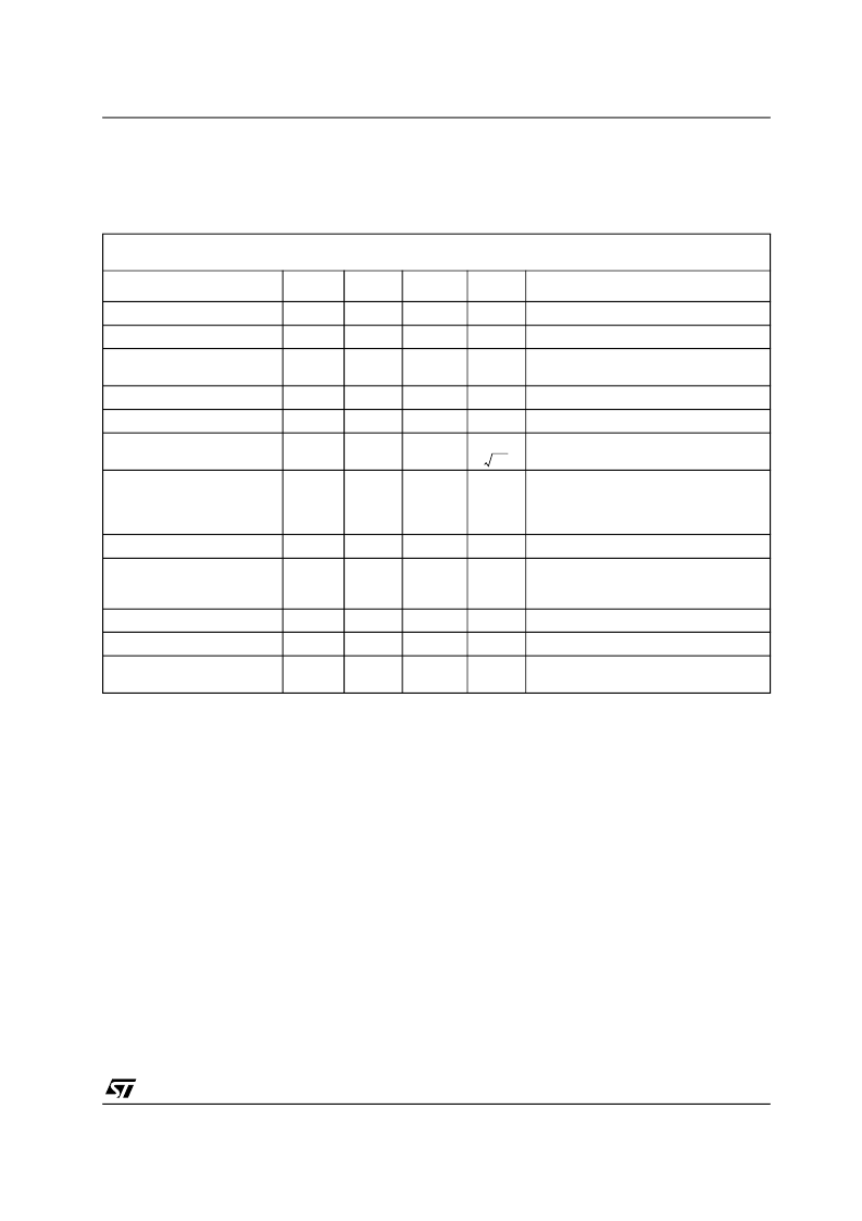
Table 9 :
Receive Path Specifications
Typical specifications apply for VCC = 5.0V, temperature = 27°C, nominal process and bias current. Maximum and
minimum performance is with VCC ±5%, 0°C < T
ambient
< 70°C, and worst case process and bias current.
Description
Min.
Typ.
Max.
Unit
Comments
Output word rate
8.832
MHz
Data Sampling frequency
Output word resolution 16 bits
16
bits
Reference Input signal
a
-0.8
-0.4
0
dBfs
Fref=138KHz, PGA gain=0dB, Vin = 0dBr
(2.4Vpd)
Common mode voltage
2.4
2.5
2.6
V
Measured on each single input
Differential Input impedance
12
20
28
k
Hz
Between RXN and RXP
Input noise
b
15
@gain=+31dB, frequency>138KHz
Gain, 0
≤
D
≤
31
Step size 1dB
c
D-0.5
D
D+0.5
dB
Receive Programmable gain. D is the
binary value of the control word. (see
Section 4.7.1.1 - Rx Gain Control on
page 10
Step size
0.8
1
1.2
dB
Attenuator 0 >= Att >= -3
Step size 4dB
d
4*Att-0.5
4*Att
4*Att+0.5
dB
Receive attenuator ATT is the binary
value of the control word. (see Section
4.7.1.1 - Rx Gain Control on page 10
Att step size
3.5
4
4.5
dB
AAF cutoff frequency
1
1.4
2
MHz
-3dB corner vs low frequency
Output SDR
2 tones
e
66
dBc
For RxPGA gain=31dB, measured at
output of ADC.
--nV
相關(guān)PDF資料 |
PDF描述 |
|---|---|
| ST70136B | CPE ADSL ANALOG FRONT END |
| ST70136G | CPE ADSL ANALOG FRONT END |
| ST70137 | UNICORNTM PCI & USB CONTROLLERLESS ADSL DMT TRANSCEIVER |
| ST70137TQFP | UNICORNTM PCI & USB CONTROLLERLESS ADSL DMT TRANSCEIVER |
| ST7250 | 8-BIT MCU FOR CAN WITH 32K ROM, 1K RAM, EEPROM, ADC, WDG, PWM/BRM, 2 TIMERS, SPI AND SCI INTERFACES |
相關(guān)代理商/技術(shù)參數(shù) |
參數(shù)描述 |
|---|---|
| ST70136B | 制造商:STMICROELECTRONICS 制造商全稱:STMicroelectronics 功能描述:CPE ADSL ANALOG FRONT END |
| ST70136G | 制造商:STMICROELECTRONICS 制造商全稱:STMicroelectronics 功能描述:CPE ADSL ANALOG FRONT END |
| ST70136Q | 功能描述:射頻無線雜項(xiàng) ADSL Analg Front-End RoHS:否 制造商:Texas Instruments 工作頻率:112 kHz to 205 kHz 電源電壓-最大:3.6 V 電源電壓-最小:3 V 電源電流:8 mA 最大功率耗散: 工作溫度范圍:- 40 C to + 110 C 封裝 / 箱體:VQFN-48 封裝:Reel |
| ST70137 | 制造商:STMicroelectronics 功能描述: |
| ST70137TQFP | 制造商:STMICROELECTRONICS 制造商全稱:STMicroelectronics 功能描述:UNICORNTM PCI & USB CONTROLLERLESS ADSL DMT TRANSCEIVER |
發(fā)布緊急采購,3分鐘左右您將得到回復(fù)。