- 您現(xiàn)在的位置:買賣IC網(wǎng) > PDF目錄385879 > STV1601A (意法半導(dǎo)體) SERIAL INTERFACE TRANSMISSION ENCODER PDF資料下載
參數(shù)資料
| 型號(hào): | STV1601A |
| 廠商: | 意法半導(dǎo)體 |
| 英文描述: | SERIAL INTERFACE TRANSMISSION ENCODER |
| 中文描述: | 串行接口傳輸編碼器 |
| 文件頁(yè)數(shù): | 13/17頁(yè) |
| 文件大小: | 244K |
| 代理商: | STV1601A |
第1頁(yè)第2頁(yè)第3頁(yè)第4頁(yè)第5頁(yè)第6頁(yè)第7頁(yè)第8頁(yè)第9頁(yè)第10頁(yè)第11頁(yè)第12頁(yè)當(dāng)前第13頁(yè)第14頁(yè)第15頁(yè)第16頁(yè)第17頁(yè)
25
D0Y
D0X
V
STV1601A
24
23
22
D1X
D1Y
EE
6
21
8-bit Parallel Data
10k
1
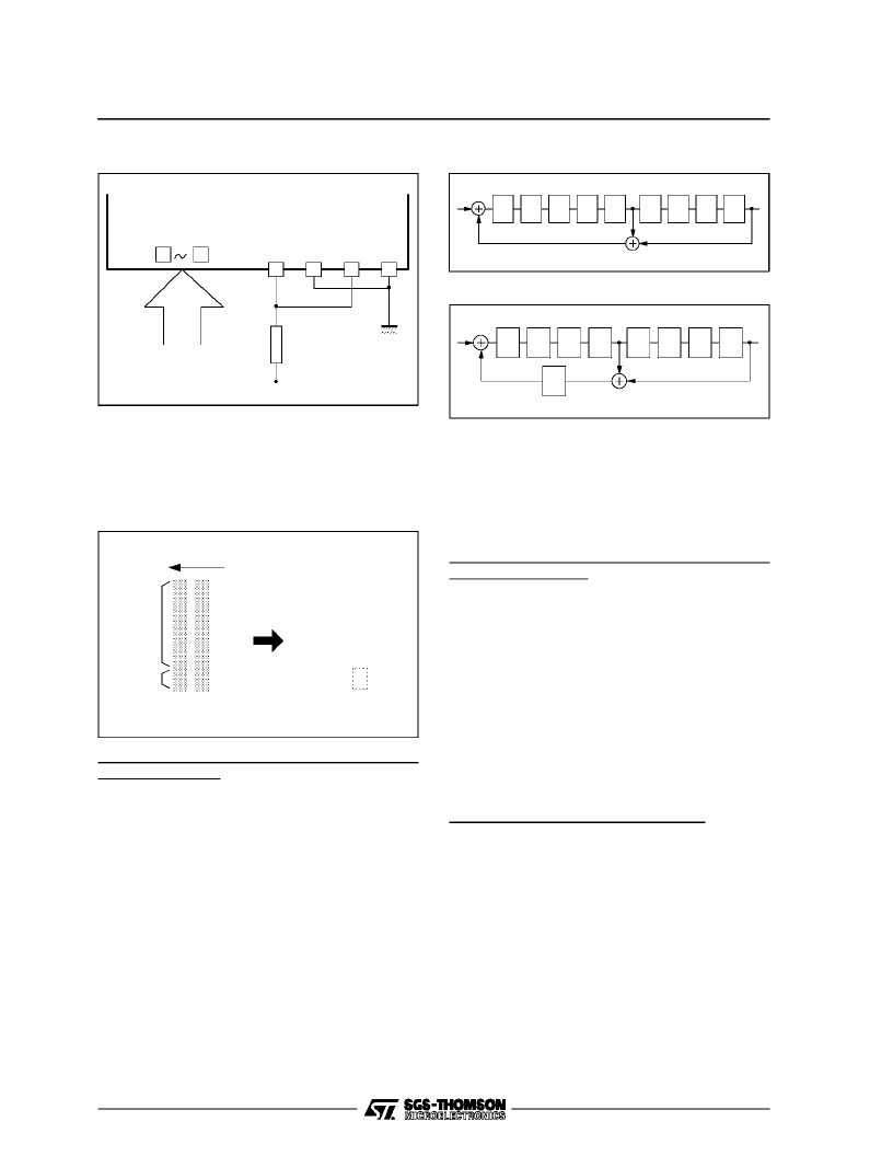
Figure14 :
8-bit Parallel Input Data (ECLlevel)
The conversion algorithm detects 2 successive
000H words andsetsthe twoLSBs of the previous
word,which is supposedto be FF, according to the
standard.
0
0
0
0
0
0
0
0
0
0
0
0
0
0
0
0
0
0
0
0
1
1
1
1
1
1
1
1
0
0
Input Data
Fixed Data
0
0
0
0
0
0
0
0
0
0
0
0
0
0
0
0
0
0
0
0
1
1
1
1
1
1
1
1
1
1
MSB
LSB
Input Order
Parallel Data after Conversion
Input ParallelData
1
Figure10 :
Conversionfrom 8-bit TRS to
10-bit TRS
Conversion in the case of more than three succes-
sive ”000H” words.
If more than 3 consecutive words of 000 in D1
standard, or 4 consecutive words of 000 in D2
standardoccur at the parallelinput (illegal accord-
ing to the standard), thus no proper operation is
possible.
5. Scramblingand NRZ to NRZI conversion
Figures16 and 17 show the scrambling circuit,the
scrambling polynomialis as follows : x
9
+ x
4
+ 1.
D1
D2
D3
D4
D5
D6
D7
D8
D9
1
Figure16 :
(x
9
+ x
4
+1) Basic Scrambling Circuit
D1
D2
D3
D4
D5
D6
D7
D8
D9
1
Figure 17 :
(x
9
+ x
4
+1) Basic Scrambling Circuit
To eliminatesignal polarityofscrambleddata, con-
versionfromNRZto NRZI isperformed (Figures18
and 19).
Therefore, the polarity for output distribution or
receiving is not needed. This allows easy system
design. The NRZ to NRZI polynominalis x + 1.
VCO temperature compensation and oscillation
frequencyadjustment
VCO oscillation frequency depends on the tem-
perature as shown in Figures 22 and 23 ”Repre-
sentative characteristics examples”. Within the
normal range of operation, frequency increases
with temperature.FV voltage remains almost con-
stant regardless of temperature.Figure 20 shows
an exampleof atemperature compensationcircuit
using a diode (transistor with C-B diode short-cir-
cuited) and a resistorconnected between FV and
V
EE
. Examplesof representativecharacteristicsfor
various temperaturesare shown in Figures 22 and
23concerningoscillationfrequencyandPLLpull-in
range (signal frequency 270, 177and 143MHz).
VCO free running frequencyadjustment
VCO free running frequency adjustment is per-
formed at room temperature.
If TN1 is set High, VCO free runs. Wait for 5 to
10 minutes after turning power supply ON (warm
up time). While monitoring PCK output (Pin 36)
adjust the signal frequency (within
±
1%) with the
variable resistor connectedbetween FV andV
EE
.
STV1601A
13/17
相關(guān)PDF資料 |
PDF描述 |
|---|---|
| STV60NE06-16 | N - CHANNEL 60V - 0.013ohm - 60A PowerSO-10 STripFET POWER MOSFET |
| STV6400 | DOUBLE SCART INTERFACE |
| STV6400D | DOUBLE SCART INTERFACE |
| STV6410A | AUDIO/VIDEO SWITCH MATRIX |
| STV6410AD | AUDIO/VIDEO SWITCH MATRIX |
相關(guān)代理商/技術(shù)參數(shù) |
參數(shù)描述 |
|---|---|
| STV1602A | 制造商:Panasonic Industrial Company 功能描述:IC- LOGIC (OTHE |
| STV160NF02L | 制造商:STMICROELECTRONICS 制造商全稱:STMicroelectronics 功能描述:N - CHANNEL 20V - 0.0016ohm - 160A - PowerSO-10 STripFET MOSFET |
| STV160NF02L_04 | 制造商:STMICROELECTRONICS 制造商全稱:STMicroelectronics 功能描述:N - CHANNEL 20V - 0.0016ohm - 160A - PowerSO-10 STripFET MOSFET |
| STV160NF02LA | 制造商:未知廠家 制造商全稱:未知廠家 功能描述:N-CHANNEL 20V 0.0018 OHM 160A POWERSO-10 STRIPFET POWER MOSFET |
| STV160NF02LAT4 | 功能描述:MOSFET N-Ch 20 Volt 160 Amp RoHS:否 制造商:STMicroelectronics 晶體管極性:N-Channel 汲極/源極擊穿電壓:650 V 閘/源擊穿電壓:25 V 漏極連續(xù)電流:130 A 電阻汲極/源極 RDS(導(dǎo)通):0.014 Ohms 配置:Single 最大工作溫度: 安裝風(fēng)格:Through Hole 封裝 / 箱體:Max247 封裝:Tube |
發(fā)布緊急采購(gòu),3分鐘左右您將得到回復(fù)。