- 您現(xiàn)在的位置:買賣IC網(wǎng) > PDF目錄383849 > SWE05-12FC Silicon Rectifier Diodes PDF資料下載
參數(shù)資料
| 型號: | SWE05-12FC |
| 英文描述: | Silicon Rectifier Diodes |
| 中文描述: | SCHALTNETZTEIL |
| 文件頁數(shù): | 6/13頁 |
| 文件大?。?/td> | 431K |
| 代理商: | SWE05-12FC |
SWE Series
AC-DC Converters <40 Watt
Benign Environment
Edition 4/4.99
6/13
MELCHER
The Power Partners.
Electromagnetic Compatibility (EMC)
A metal oxide VDR together with an input fuse and an input
filter form an effective protection against high input tran-
sient voltages which typically occur in most installations,
but especially in battery driven mobile applications. The
SWE series has been successfully tested to the following
specifications:
Electromagnetic Immunity
Table 5: Immunity type tests
Phenomenon
Standard
1
Level
Coupling
mode
2
Value
applied
Waveform
Source
imped.
Test
In
Per-
procedure
oper. form.
3
Electrostatic
discharge
IEC/EN
61000-4-2
x
air discharge
to frame
6000 V
p
1/50 ns
330
10 positive and
10 negative
discharges
yes
4
Electromagnetic
field
IEC/EN
61000-4-3
x
antenna in
1 m distance
10 V/m
sine wave modu-
lated w. 1 kHz
26
…
1000 MHz
yes
4
Electrical fast
transient/burst
IEC/EN
61000-4-4
x
i/c, +i/
–
i
2000 V
p
5/50 ns
50
1 min positive
1 min negative
transients per
coupling mode
yes
4
Surge
IEC/EN
61000-4-5
x
i/c
2000 V
p
1.2/50
μ
s
12
5 pos. and 5 neg.
surges per
coupling mode
yes
4
1
Related and previous standards are referenced in: Technical Information: Standards
2
i = input, o = output, c = case.
3
A = Normal operation, no deviation from specifications, B = Temporary deviation from specs possible.
4
Normal operation, no deviation from specifications.
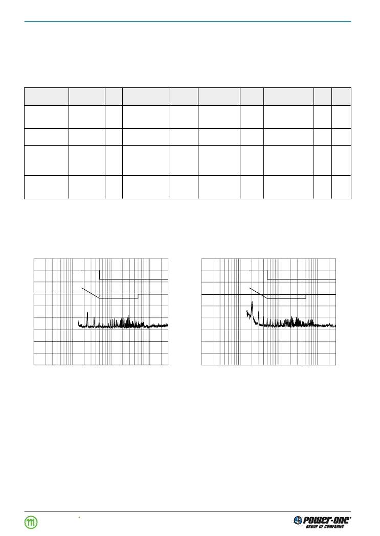
Fig. 4
Typical disturbance voltage (quasi-peak) at the input accord-
ing to CISPR 11/22 and EN 55011/22, measured at U
i nom
and I
o nom
. e.g. SWE 05-05FC
90
80
70
60
50
40
30
20
10
0
0
0
0
0
1
5
1
2
3
[dB
μ
V]
MHz
0
07073
A
B
90
80
70
60
50
40
30
20
10
0
0
0
0
0
1
5
1
2
3
[dB
μ
V]
MHz
0
07074
A
B
Fig. 5
Typical disturbance voltage (quasi-peak) at the input accord-
ing to CISPR 11/22 and EN 55011/22, measured at U
i nom
and I
o nom
. e.g. SWE 10-05FC
Electromagnetic Emissions
相關(guān)PDF資料 |
PDF描述 |
|---|---|
| SWE10-05FC | Silicon Rectifier Diodes |
| SWE10-12FC | Silicon Rectifier Diodes |
| SWE10-24FC | Silicon Rectifier Diodes |
| SWE15-05FC | Silicon Rectifier Diodes |
| SWE15-12FC | Silicon Rectifier Diodes |
相關(guān)代理商/技術(shù)參數(shù) |
參數(shù)描述 |
|---|---|
| SWE10 | 功能描述:電位計 RESISTIVE & OPTICAL SWITCHES SPST RoHS:否 制造商:Bourns 產(chǎn)品:Musical Syst Potentiometer 安裝風(fēng)格:Panel 錐度:Audio, Linear 轉(zhuǎn)數(shù): 電阻:500 kOhms 元件類型:Carbon 軸類型:Round / Plain 端接類型:Solder Lug 電壓額定值:200 V 功率額定值:0.2 W 容差:20 % |
| SWE-10 | 制造商:Honeywell Sensing and Control 功能描述: |
| SWE10-05FC | 制造商:未知廠家 制造商全稱:未知廠家 功能描述:SCHALTNETZTEIL |
| SWE10-12FC | 制造商:未知廠家 制造商全稱:未知廠家 功能描述:SCHALTNETZTEIL |
| SWE10-24FC | 制造商:未知廠家 制造商全稱:未知廠家 功能描述:SCHALTNETZTEIL |
發(fā)布緊急采購,3分鐘左右您將得到回復(fù)。