- 您現(xiàn)在的位置:買賣IC網(wǎng) > PDF目錄361357 > T66H0001A-Y (TM Technology, Inc.) 240 output LCD Segment/Common Driver IC PDF資料下載
參數(shù)資料
| 型號(hào): | T66H0001A-Y |
| 廠商: | TM Technology, Inc. |
| 英文描述: | 240 output LCD Segment/Common Driver IC |
| 中文描述: | LCD段輸出240 /共同驅(qū)動(dòng)器IC |
| 文件頁數(shù): | 22/35頁 |
| 文件大小: | 343K |
| 代理商: | T66H0001A-Y |
第1頁第2頁第3頁第4頁第5頁第6頁第7頁第8頁第9頁第10頁第11頁第12頁第13頁第14頁第15頁第16頁第17頁第18頁第19頁第20頁第21頁當(dāng)前第22頁第23頁第24頁第25頁第26頁第27頁第28頁第29頁第30頁第31頁第32頁第33頁第34頁第35頁

TE
CH
tm
T66H0001A
TM Technology Inc. reserves the right
P. 22
to change products or specifications without notice. Revision:A
Publication Date: JUL. 2002
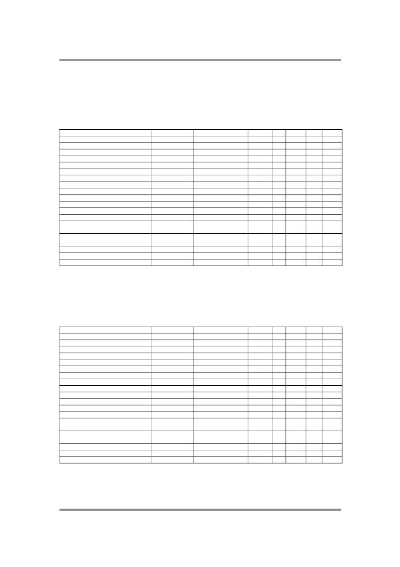
AC Characteristics
(Segment Mode 1) (Vss = V
5
= 0V, V
DD
= +5.0 ±0.5V, V
0
= +10.0 to +42.0V, T
OPR
= -20 to +85 oC)
PARAMETER
SYMBOL
Shift clock period
twck
Shift clock “H” pulse width
twckh
Shift clock “L” pulse width
twckl
Data setup time
t
DS
Data hold time
t
DH
Latch pulse “H” pulse width
t
wLPH
Shift clock rise to latch pulse rise time
t
LD
Shift clock fall to latch pulse fall time
t
SL
Latch pulse rise to shift clock rise time
t
LS
Latch pulse fall to shift clock fall time
t
LH
Enable setup time
ts
Input signal rise time
t
R
Input signal fall time
t
F
/DISPOFF removal time
/DISPOFF “L” pulse width
Output delay time (1)
t
D
Output delay time (2)
t
PD1,
t
PD2
Output delay time (3)
t
PD3
NOTES :
CONDITIONS
t
R
,t
F
10 ns
MIN.
50
15
15
10
12
15
0
30
25
25
10
TYP. MAX. UNIT NOTE
50
50
ns
ns
ns
ns
ns
ns
ns
ns
ns
ns
ns
ns
ns
1
2
2
t
SD
100
ns
t
WDL
1.2
us
C
L=
15 pF
C
L=
15 pF
C
L=
15 pF
30
1.2
1.2
ns
us
us
1. Takes the cascade connection into consideration
2. (twck - twck
H
– twck
L
)/2 is maximum in the case of high speed operation.
(Segment Mode 2) (Vss = V
5
= 0V, V
DD
= +3.0 to +4.5V, V
0
= +10.0 to +42.0V, T
OPR
= -20 to +85 oC)
PARAMETER
SYMBOL
Shift clock period
twck
Shift clock “H” pulse width
twckh
Shift clock “L” pulse width
twckl
Data setup time
t
DS
Data hold time
t
DH
Latch pulse “H” pulse width
t
wLPH
Shift clock rise to latch pulse rise time
t
LD
Shift clock fall to latch pulse fall time
t
SL
Latch pulse rise to shift clock rise time
t
LS
Latch pulse fall to shift clock fall time
t
LH
Enable setup time
ts
Input signal rise time
t
R
Input signal fall time
t
F
/DISPOFF removal time
/DISPOFF “L” pulse width
Output delay time (1)
t
D
Output delay time (2)
t
PD1,
t
PD2
Output delay time (3)
t
PD3
NOTES :
CONDITIONS
t
R
,t
F
10 ns
MIN.
66
23
23
15
23
30
0
50
30
30
15
TYP. MAX. UNIT NOTE
50
50
ns
ns
ns
ns
ns
ns
ns
ns
ns
ns
ns
ns
ns
1
2
2
t
SD
100
ns
t
WDL
1.2
us
C
L=
15 pF
C
L=
15 pF
C
L=
15 pF
41
1.2
1.2
ns
us
us
1. Takes the cascade connection into consideration
2. (twck - twck
H
– twck
L
)/2 is maximum in the case of high speed operation.
相關(guān)PDF資料 |
PDF描述 |
|---|---|
| T66H0002A | 160 output LCD Segment/Common Driver IC |
| T66H0002A-AY | 160 output LCD Segment/Common Driver IC |
| T66H0002A-Y | 160 output LCD Segment/Common Driver IC |
| T66H0004A | 80 output LCD Segment/Common Driver IC |
| T66H0004A-Q | 80 output LCD Segment/Common Driver IC |
相關(guān)代理商/技術(shù)參數(shù) |
參數(shù)描述 |
|---|---|
| T66H0002A | 制造商:TMT 制造商全稱:TMT 功能描述:160 output LCD Segment/Common Driver IC |
| T66H0002A-AY | 制造商:TMT 制造商全稱:TMT 功能描述:160 output LCD Segment/Common Driver IC |
| T66H0002A-Y | 制造商:TMT 制造商全稱:TMT 功能描述:160 output LCD Segment/Common Driver IC |
| T66H0004A | 制造商:TMT 制造商全稱:TMT 功能描述:80 output LCD Segment/Common Driver IC |
| T66H0004A1S | 制造商:TMT 制造商全稱:TMT 功能描述:80 output LCD Segment/Common Driver IC |
發(fā)布緊急采購(gòu),3分鐘左右您將得到回復(fù)。