- 您現(xiàn)在的位置:買賣IC網(wǎng) > PDF目錄98158 > TA8795BF SPECIALTY CONSUMER CIRCUIT, PQFP60 PDF資料下載
參數(shù)資料
| 型號: | TA8795BF |
| 元件分類: | 消費家電 |
| 英文描述: | SPECIALTY CONSUMER CIRCUIT, PQFP60 |
| 封裝: | 14 X 14 MM, 0.80 MM PITCH, PLASTIC, QFP-60 |
| 文件頁數(shù): | 30/45頁 |
| 文件大?。?/td> | 1139K |
| 代理商: | TA8795BF |
第1頁第2頁第3頁第4頁第5頁第6頁第7頁第8頁第9頁第10頁第11頁第12頁第13頁第14頁第15頁第16頁第17頁第18頁第19頁第20頁第21頁第22頁第23頁第24頁第25頁第26頁第27頁第28頁第29頁當前第30頁第31頁第32頁第33頁第34頁第35頁第36頁第37頁第38頁第39頁第40頁第41頁第42頁第43頁第44頁第45頁
TA8795BF
2001-01-15 36/45
TEST CONDITIONS : VCC = 5V, Ta = 25±3°C
SW No. AND VR MODE
No.
PARAMETER SYMBOL
UNIT
MIN
TYP.
MAX
15
16
18
19
21
24
31
34
38
47
55
TEST METHOD
C29
PAL ID
malfunction
check
V20P
V20N3
V20N4
V20S
V20BW
V
―
4.20
2.00
―
Open
A
Open
A
Open Open Open OFF Open
C30
NTSC ID
malfunction
check
V17P
V17N3
V17N4
V17S
V17BW
V
―
4.20
2.00
―
Open
A
Open
A
Open Open Open OFF Open
C31
SECAM ID
malfunction
check
V29P
V29N3
V29N4
V29S
V29BW
V
―
2.25
2.10
3.90
2.15
―
Open
A
Open
A
Open Open Open OFF Open
1. Input the signals corresponding to each mode to
pins 21 (PAL / NTSC) and 24 (SECAM) (75%
standard color bar signal).
2. Measure the N / P / S ID DC voltage on pins 17,
20, and 29.
P
: Philips pattern signal
N3
: 3.58N 75% standard color bar signal
N4
: 4.43N 75% standard color bar ignal
S
: SECAM 75% standard color bar signal
Black & white: RETMA signal
Note: When measuring the filtered voltage,
measure at high impedance (at least 10M
or higher).
C32
Color control
adjustment
range
V34
V
―
3.50
―
Open
A
Open
A
B
Open Adjust Open OFF Open
C33
Color control
adjustment
voltage
V34
V
―
2.50
―
Open
A
Open
A
B
Open Adjust Open OFF Open
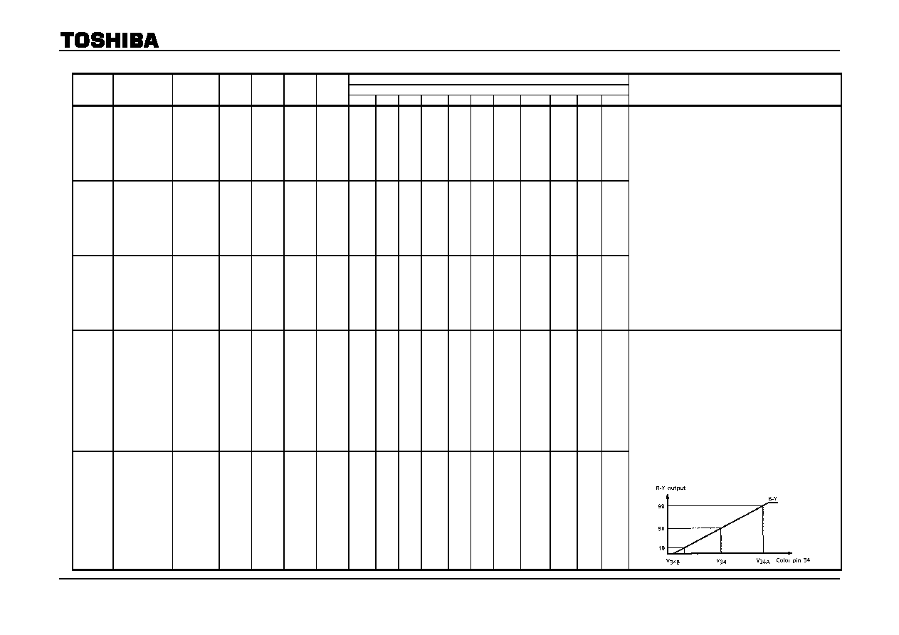
1. To pin 21, input burst and chroma signals with the
same amplitude (100mVp-p) (rainbow color bar
signal).
2. While measuring the pin 43 B-Y, adjust so that the
6 bar reaches the peak using the tint control VR.
Vary the color control VR under the above
conditions and define the color control pin voltage
as V34 where the B-Y output amplitude halves.
Also, where the B-Y output amplitudes are 90%
and 10%, define the color control pin voltages as
V34A and V34B respectively. And define the
voltage difference between V34A and V34B as
V34, the color control range.
V34 = V34AV34B
相關PDF資料 |
PDF描述 |
|---|---|
| TA8800N | AUDIO/VIDEO DEMODULATOR, PDIP24 |
| TA8801AN | SPECIALTY CONSUMER CIRCUIT, PDIP36 |
| TA8805F | AM/FM, AUDIO/VIDEO DEMODULATOR, PDSO24 |
| TA1207F | AM/FM, AUDIO/VIDEO DEMODULATOR, PDSO24 |
| TA8814N | SPECIALTY CONSUMER CIRCUIT, PDIP20 |
相關代理商/技術參數(shù) |
參數(shù)描述 |
|---|---|
| TA8796N | 制造商:TOSHIBA 制造商全稱:Toshiba Semiconductor 功能描述:PIF QIF SYSTEM FOR TV |
| TA8797BH | 制造商:Rochester Electronics LLC 功能描述:- Bulk |
| TA8800 | 制造商:TOSHIBA 制造商全稱:Toshiba Semiconductor 功能描述:PLL PIF/SIF IC FOR TV/VTR |
| TA8800N | 制造商:TOSHIBA 制造商全稱:Toshiba Semiconductor 功能描述:PLL PIF/SIF IC FOR TV/VTR |
| TA8800N_01 | 制造商:TOSHIBA 制造商全稱:Toshiba Semiconductor 功能描述:PLL PIF/SIF IC FOR TV/VTR |
發(fā)布緊急采購,3分鐘左右您將得到回復。