- 您現(xiàn)在的位置:買賣IC網(wǎng) > PDF目錄98170 > TC642BEOA713 BRUSHLESS DC MOTOR CONTROLLER, PDSO8 PDF資料下載
參數(shù)資料
| 型號: | TC642BEOA713 |
| 元件分類: | 運(yùn)動(dòng)控制電子 |
| 英文描述: | BRUSHLESS DC MOTOR CONTROLLER, PDSO8 |
| 封裝: | 0.150 INCH, PLASTIC, SOIC-8 |
| 文件頁數(shù): | 6/34頁 |
| 文件大小: | 683K |
| 代理商: | TC642BEOA713 |
第1頁第2頁第3頁第4頁第5頁當(dāng)前第6頁第7頁第8頁第9頁第10頁第11頁第12頁第13頁第14頁第15頁第16頁第17頁第18頁第19頁第20頁第21頁第22頁第23頁第24頁第25頁第26頁第27頁第28頁第29頁第30頁第31頁第32頁第33頁第34頁

TC642B/TC647B
DS21756B-page 14
2003 Microchip Technology Inc.
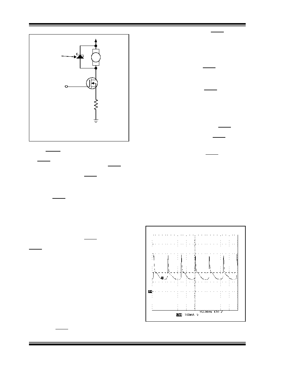
FIGURE 4-5:
Clamp Diode for Fan.
4.7
FAULT Output
The FAULT output is an open-drain, active-low output.
For the TC642B and TC647B devices, the FAULT out-
put indicates when a fan fault condition has occurred.
For the TC642B device, the FAULT output also indi-
cates when an over-temperature (OTF) condition has
occurred.
For the TC642B device, an over-temperature condition
is indicated (FAULT output is pulled low) when the VIN
input reaches the VOTF threshold voltage (the VOTF
threshold voltage is typically 20 mV higher than the
VCMAX threshold and has 80 mV of hysteresis). This
indicates that maximum cooling capacity has been
reached (the fan is at full speed) and that an overheat-
ing situation can occur. When the voltage at the VIN
input falls below the VOTF threshold voltage by the hys-
teresis value (VOTF-HYS), the FAULT output returns to
the high-state (a pull-up resistor is needed on the
FAULT output).
A fan fault condition is indicated when fan current
pulses are no longer detected at the SENSE pin.
Pulses at the SENSE pin indicate that the fan is
spinning and conducting current.
If pulses are not detected at the SENSE pin for 32 PWM
cycles, the 3-cycle diagnostic timer is fired. This means
that the VOUT output is high for 3 PWM cycles. If pulses
are detected in this 3-cycle period, then normal PWM
operation is resumed and no fan fault is indicated. If no
pulses are detected in the 3-cycle period, the start-up
timer is activated and the VOUT output is driven high for
32 PWM cycles. If pulses are detected during this time-
frame, normal PWM operation is resumed. If no pulses
are detected during this time frame, a fan fault condition
exists and the FAULT output is pulled low.
During a fan fault condition, the FAULT output will
remain low until the fault condition has been removed.
During this time, the VOUT output is driven high contin-
uously to attempt to restart the fan, and the SENSE pin
is monitored for fan pulses. If a minimum of 16 pulses
are detected at the SENSE input over a 32 cycle time
period (one second for CF = 1.0 F), the fan fault con-
dition no longer exists. The FAULT output is then
released and the VOUT output returns to normal PWM
operation, as dictated by the VIN and VMIN inputs.
If the VMIN voltage is pulled below the VSHDN level dur-
ing a fan fault condition, the FAULT output will be
released and the VOUT output will be shutdown
(VOUT = 0V). If the VMIN voltage then increases above
the VREL threshold, the device will go through the
normal start-up routine.
If, during a fan fault condition, the voltage at the VIN pin
drops below the VMIN voltage level, the TC642B/
TC647B device will continue to hold the FAULT line low
and drive the VOUT output to 100% duty cycle. If the fan
fault condition is then removed, the FAULT output will
be released and the VOUT output will be driven to the
duty cycle that is being commanded by the VMIN input.
The sink current capability of the FAULT output is listed
in the “Electrical Characteristics” table of Section 1.0.
4.8
Sensing Fan Operation (SENSE)
The SENSE input is an analog input used to monitor
the fan’s operation. It does this by sensing fan current
pulses, which represent fan rotation. When a fan
rotates, commutation of the fan current occurs as the
fan poles pass the armatures of the motor. The commu-
tation of the fan current makes the current waveshape
appear as pulses. There are two typical current wave-
forms of brushless DC fan motors. These are shown in
FIGURE 4-6:
Fan Current With DC Offset
And Positive Commutation Current.
Q1
GND
RSENSE
VOUT
Q1: N-Channel MOSFET
FAN
Clamp Diode
相關(guān)PDF資料 |
PDF描述 |
|---|---|
| TC647BEUA | BRUSHLESS DC MOTOR CONTROLLER, PDSO8 |
| TC642BEOA | BRUSHLESS DC MOTOR CONTROLLER, PDSO8 |
| TC647EOATR | BRUSHLESS DC MOTOR CONTROLLER, PDSO8 |
| TC647VUATR | BRUSHLESS DC MOTOR CONTROLLER, PDSO8 |
| TC647VOART | BRUSHLESS DC MOTOR CONTROLLER, PDSO8 |
相關(guān)代理商/技術(shù)參數(shù) |
參數(shù)描述 |
|---|---|
| TC642BEOAG | 制造商:Microchip Technology 功能描述:Fan Control Demo Board |
| TC642BEOATR | 制造商:MICROCHIP 制造商全稱:Microchip Technology 功能描述:PWM Fan Speed Controllers With Minimum Fan Speed, Fan Restart and FanSense⑩ Technology for Fault Detection |
| TC642BEPA | 功能描述:馬達(dá)/運(yùn)動(dòng)/點(diǎn)火控制器和驅(qū)動(dòng)器 w/Rstrt & Flt Dtct RoHS:否 制造商:STMicroelectronics 產(chǎn)品:Stepper Motor Controllers / Drivers 類型:2 Phase Stepper Motor Driver 工作電源電壓:8 V to 45 V 電源電流:0.5 mA 工作溫度:- 25 C to + 125 C 安裝風(fēng)格:SMD/SMT 封裝 / 箱體:HTSSOP-28 封裝:Tube |
| TC642BEPA713 | 制造商:MICROCHIP 制造商全稱:Microchip Technology 功能描述:PWM Fan Speed Controllers With Minimum Fan Speed, Fan Restart and FanSense⑩ Technology for Fault Detection |
| TC642BEPATR | 制造商:MICROCHIP 制造商全稱:Microchip Technology 功能描述:PWM Fan Speed Controllers With Minimum Fan Speed, Fan Restart and FanSense⑩ Technology for Fault Detection |
發(fā)布緊急采購,3分鐘左右您將得到回復(fù)。