- 您現(xiàn)在的位置:買賣IC網(wǎng) > PDF目錄373617 > TDA2040 (意法半導(dǎo)體) 20W Hi-Fi AUDIO POWER AMPLIFIER PDF資料下載
參數(shù)資料
| 型號(hào): | TDA2040 |
| 廠商: | 意法半導(dǎo)體 |
| 英文描述: | 20W Hi-Fi AUDIO POWER AMPLIFIER |
| 中文描述: | 20瓦高保真音頻功率放大器 |
| 文件頁(yè)數(shù): | 10/13頁(yè) |
| 文件大小: | 391K |
| 代理商: | TDA2040 |
第1頁(yè)第2頁(yè)第3頁(yè)第4頁(yè)第5頁(yè)第6頁(yè)第7頁(yè)第8頁(yè)第9頁(yè)當(dāng)前第10頁(yè)第11頁(yè)第12頁(yè)第13頁(yè)
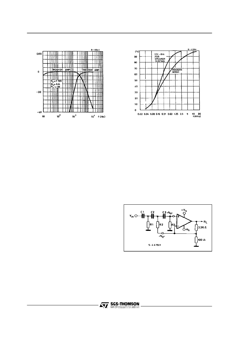
Figure18 :
Frequency Response
Figure 19 :
Power Distribution versus Frequency
MULTIWAY SPEAKER SYSTEMS AND ACTIVE
BOXES
Multiway loudspeaker systems provide the best
possible acoustic performance since each loud-
speaker is specially designed and optimized to
handle a limited range of frequencies.Commonly,
these loudspeakersystems divide the audio spec-
truminto two,three or four bands.
TomaintainaflatfrequencyresponseovertheHi-Fi
audio range the bands covered by each loud-
speakermust overlapslightly. Imbalancebetween
the loudspeakers produces unacceptable results
therefore it is important to ensure that each unit
generates the correct amount of acoustic energy
for its segment of the audio spectrum. In this re-
spect it is also important to know the energy distri-
bution of the music spectrum determine the cutoff
frequenciesof thecrossoverfilters (see Figure 19).
As an example, a 100W three-way system with
crossover frequencies of 400Hz and 3kHz would
require 50W for the woofer, 35Wfor the midrange
unit and 15W for the tweeter.
Both active and passive filters can be used for
crossovers but today activefilters costsignificantly
less than a good passive filter using air-cored in-
ductorsandnon-electrolyticcapacitors.Inaddition,
active filters do not suffer from the typical defects
of passive filters :
- power loss
- increased impedance seen by the loudspeaker
(lower damping)
- difficulty of precise design due to variable loud-
speakerimpedance
Obviously,active crossovers can only be used if a
poweramplifieris providedforeachdriveunit.This
makes it particularly interesting and economically
soundto use monolithicpower amplifiers. In some
applications, complex filters are not really neces-
sary and simple RC low-pass and high-pass net-
works (6dB/octave)can be recommended.
The results obtained are excellent because this is
the best type of audio filter and the only one free
from phaseand transientdistortion.
The rather poor out of band attenuation of single
RC filters means that the loudspeakermust oper-
ate linearly well beyondthe crossoverfrequencyto
avoid distortion.
A more effective solution, named ”Active Power
Filter” bySGS is shownin Figure 20.
Figure 20 :
Active PowerFilter
The proposed circuit can realize combined power
amplifiers and 12dB/octave or 18dB/octave high-
pass or low-pass filters.
In practice, at the input pins of the amplifier two
equal and in-phase voltages are available, as re-
quiredfor the activefilter operation.
TDA2040
10/13
相關(guān)PDF資料 |
PDF描述 |
|---|---|
| TDA2048 | Multistandard quasi parallel-sound processor for Mono-TV-Sets |
| TDA2050H | 32W Hi-Fi AUDIO POWER AMPLIFIER |
| TDA2050V | 32W Hi-Fi AUDIO POWER AMPLIFIER |
| TDA2050 | 32W Hi-Fi Audio Amplifier(32W Hi-Fi音頻功率放大器) |
| TDA2051H | 40W Hi-Fi AUDIO POWER AMPLIFIER |
相關(guān)代理商/技術(shù)參數(shù) |
參數(shù)描述 |
|---|---|
| TDA2040_12 | 制造商:STMICROELECTRONICS 制造商全稱:STMicroelectronics 功能描述:25-watt hi-fi audio power amplifier |
| TDA2040H | 功能描述:音頻放大器 20W Hi-Fi Audio Amp RoHS:否 制造商:STMicroelectronics 產(chǎn)品:General Purpose Audio Amplifiers 輸出類型:Digital 輸出功率: THD + 噪聲: 工作電源電壓:3.3 V 電源電流: 最大功率耗散: 最大工作溫度: 安裝風(fēng)格:SMD/SMT 封裝 / 箱體:TQFP-64 封裝:Reel |
| TDA2040V | 功能描述:音頻放大器 20W Hi-Fi Audio Amp RoHS:否 制造商:STMicroelectronics 產(chǎn)品:General Purpose Audio Amplifiers 輸出類型:Digital 輸出功率: THD + 噪聲: 工作電源電壓:3.3 V 電源電流: 最大功率耗散: 最大工作溫度: 安裝風(fēng)格:SMD/SMT 封裝 / 箱體:TQFP-64 封裝:Reel |
| TDA2040V | 制造商:STMicroelectronics 功能描述:AUDIO AMP 22W 2040 PENTAWATT-5 |
| TDA2048 | 制造商:TEMIC 制造商全稱:TEMIC Semiconductors 功能描述:Multistandard quasi parallel-sound processor for Mono-TV-Sets |
發(fā)布緊急采購(gòu),3分鐘左右您將得到回復(fù)。