- 您現(xiàn)在的位置:買賣IC網(wǎng) > PDF目錄373630 > TEA7530DP (意法半導(dǎo)體) MONITOR AMPLIFIER PDF資料下載
參數(shù)資料
| 型號(hào): | TEA7530DP |
| 廠商: | 意法半導(dǎo)體 |
| 英文描述: | MONITOR AMPLIFIER |
| 中文描述: | 顯示器放大器 |
| 文件頁(yè)數(shù): | 6/11頁(yè) |
| 文件大小: | 118K |
| 代理商: | TEA7530DP |
Amplifier DC Supply
In transmission mode, the supply voltage is con-
trolled by the internal shunt DC regulator.For this
reason, the TEA7530 should be supplied from a
current source (see: supply considerations).
An antidistortion system is embodied which pro-
vides AGC control to avoid loudspeakerdistortion
under current-limited conditions.
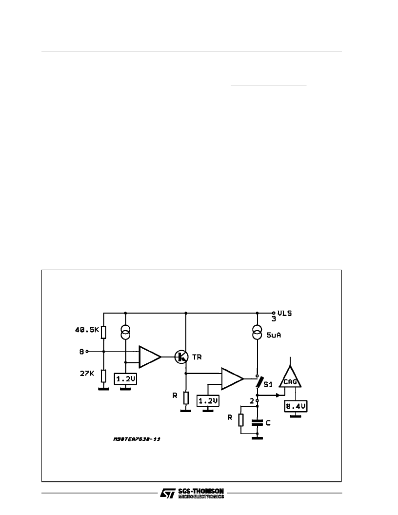
AGC Circuitaction
When the supply V
LS
is insufficient, the voltage at
pin 8, falls below the reference voltage 1.2V, re-
sulting in transistor (TR) being switched off, re-
sulting zero current flow in resistor R. This state
enables the gain control system. Under these
conditions, the shunt DC supply will switch at a
rate determined by the time constant of the RC
networkon pin2.
This
switching
action
speech characteristic under low supply condi-
tions.
The AGC will be switched ON when the level on
Pin 2 is greaterthan a referencevoltageof 0.4V.
accomodates
normal
Supply Considerations
a) Current MODE - Pin 8 is open (V
LS
= V
LS1
) or
connected to ground with an external resistor
(R
ext
) higher than 16K
. The typical value of V
LS
is :
V
LS
= 1.2V40.5K
+ (
27K
R
EXT
)
(
27K
R
)
The AGC section is working as described in the
previousparagraph.
b) Voltage MODE - Pin 8 is shorted or connected
to GND with a resistor(R
EXT
) lower than 16K
. In
this condition the circuit must be supplied with a
DC voltage of 3 to 5.5V. In this case the AGC
sectionis permanentlyON. Pin 2 must be shorted
to GND (in voltage mode only) to avoid perma-
nent attenuationof the signal at audio input
.
PIN FUNCTIONS
PIN1
: GND.
PIN2:
AUTOMATIC GAIN CONTROL FILTER
The antidistortion system response is adjusted by
the R-C networkon thispin.
The AGC will be switched ON when the level on
pin 2 is greater than a reference voltage of 0.4V,
the RC-network charges (current source ON) or
discharges (current source OFF) according to
supplyvoltage.
Figure11
TEA7530
6/11
相關(guān)PDF資料 |
PDF描述 |
|---|---|
| TEA7530FP | MONITOR AMPLIFIER |
| TEA7530 | Monitor Amplifier(監(jiān)聽(tīng)放大器) |
| TEA7532DP | MONITOR AMPLIFIER |
| TEA7532FP | MONITOR AMPLIFIER |
| TEA7532 | Monitor Amplifier(監(jiān)聽(tīng)放大器) |
相關(guān)代理商/技術(shù)參數(shù) |
參數(shù)描述 |
|---|---|
| TEA7530FP | 制造商:STMICROELECTRONICS 制造商全稱:STMicroelectronics 功能描述:MONITOR AMPLIFIER |
| TEA7531 | 制造商:STMICROELECTRONICS 制造商全稱:STMicroelectronics 功能描述:MONITOR AMPLIFIER |
| TEA7532 | 制造商:STMICROELECTRONICS 制造商全稱:STMicroelectronics 功能描述:MONITOR AMPLIFIER |
| TEA7532DP | 制造商:STMICROELECTRONICS 制造商全稱:STMicroelectronics 功能描述:MONITOR AMPLIFIER |
| TEA7532FP | 制造商:STMICROELECTRONICS 制造商全稱:STMicroelectronics 功能描述:MONITOR AMPLIFIER |
發(fā)布緊急采購(gòu),3分鐘左右您將得到回復(fù)。