- 您現(xiàn)在的位置:買賣IC網(wǎng) > PDF目錄361487 > TK65913M (TOKO Inc.) SMALL EL LAMP DRIVER PDF資料下載
參數(shù)資料
| 型號: | TK65913M |
| 廠商: | TOKO Inc. |
| 英文描述: | SMALL EL LAMP DRIVER |
| 中文描述: | 小發(fā)光燈驅(qū)動器 |
| 文件頁數(shù): | 2/20頁 |
| 文件大小: | 203K |
| 代理商: | TK65913M |

Page 2
May 2000 TOKO, Inc.
TK6591x
Note 1: Power dissipation is 600 mW when mounted as recommended (200 mW In Free Air). Derate at 4.8 mW/
°
C for operation above 25
°
C.
Note 2: Converter supply current is dependent upon the DC resistance of inductor L
1
. Lower DC resistances will result in lower supply currents.
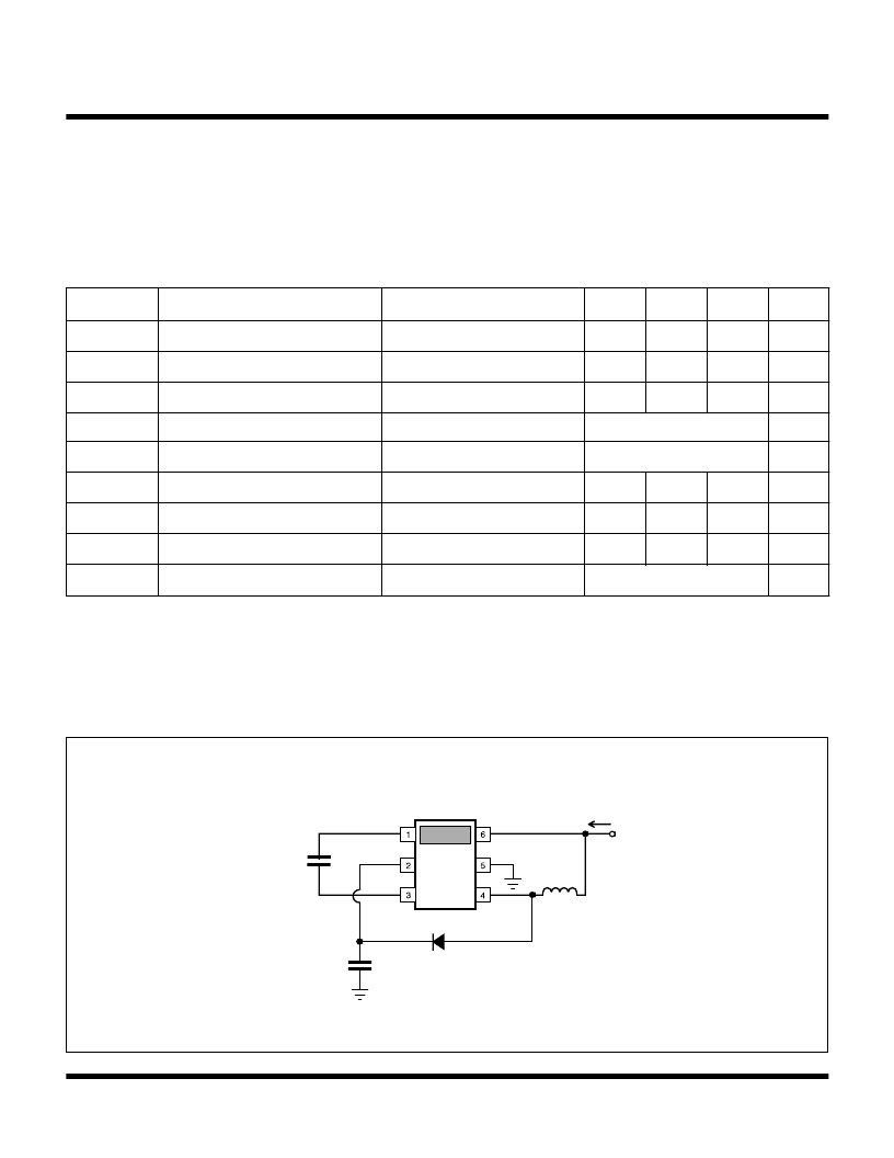
Note 3: When using test circuit below.
Gen. Note: Refer to “INDUCTOR VALUE SELECTION” and “INDUCTOR TYPE SELECTION” of Design Considerations Section for choosing
inductor.
TK6591x ELECTRICAL CHARACTERISTICS
V
CC
= 3.6 V, T
A
= T
j
= 25
°
C, unless otherwise specified.
ABSOLUTE MAXIMUM RATINGS
V
CC
Pin .................................................................... 6.5 V
All Pins Except V
CC
and GND ...............................V
CLAMP
Power Dissipation (Note 1) ................................ 600 mW
Storage Temperature Range ................... -55 to +150
°
C
Operating Temperature Range ...................-30 to +80
°
C
Junction Temperature ...........................................150
°
C
SYMBOL
PARAMETER
TEST CONDITIONS
MIN
TYP
MAX
UNITS
V
CC
Input Supply Range
2.7
3.6
6
V
I
Q
Quiescent Current
Current into pin 6
200
μA
I
PEAK
Peak Current Threshold
26
32
38
mA
F
LAMP
Lamp Frequency
See Table 1
Hz
F
BOOST
Boost Frequency
See Table 2
kHz
V
CLAMP
Boost Clamp Voltage
Force 100 μA into HV pin
90
105
120
V
D
(MAX)
Maximum Duty Cycle
88
92
96
%
V
OUT
Peak to Peak Lamp Voltage
(Note 3)
125
140
155
V
I
CONV
Converter Supply Current
(Notes 2, 3)
See Table 3
mA
TEST CIRCUIT
CEL
5 nF
VCC
C1
22 nF
D1
EL +
HV
GND
IND
EL -
VCC
L1
820 μH
ICONV
Note: L
1
= Toko Low Profile D32FU Series: 887FU-821 M
D
1
= DIODES INC. DL4148
C
1
= AVX 12061C223KAT2A
相關PDF資料 |
PDF描述 |
|---|---|
| TK65913MTL | SMALL EL LAMP DRIVER |
| TK65914M | SMALL EL LAMP DRIVER |
| TK65914MTL | SMALL EL LAMP DRIVER |
| TK65916MTL | SMALL EL LAMP DRIVER |
| TK65917M | SMALL EL LAMP DRIVER |
相關代理商/技術參數(shù) |
參數(shù)描述 |
|---|---|
| TK65913MTL | 制造商:TOKO 制造商全稱:TOKO, Inc 功能描述:SMALL EL LAMP DRIVER |
| TK65913MTL/A3 | 制造商:TOKO 制造商全稱:TOKO, Inc 功能描述:SMALL EL LAMP DRIVER |
| TK65914M | 制造商:TOKO 制造商全稱:TOKO, Inc 功能描述:SMALL EL LAMP DRIVER |
| TK65914MTL | 制造商:TOKO 制造商全稱:TOKO, Inc 功能描述:SMALL EL LAMP DRIVER |
| TK65914MTL/A4 | 制造商:TOKO 制造商全稱:TOKO, Inc 功能描述:SMALL EL LAMP DRIVER |
發(fā)布緊急采購,3分鐘左右您將得到回復。