- 您現(xiàn)在的位置:買賣IC網(wǎng) > PDF目錄98230 > TL1451AMDREP (TEXAS INSTRUMENTS INC) 0.021 A DUAL SWITCHING CONTROLLER, 500 kHz SWITCHING FREQ-MAX, PDSO16 PDF資料下載
參數(shù)資料
| 型號: | TL1451AMDREP |
| 廠商: | TEXAS INSTRUMENTS INC |
| 元件分類: | 穩(wěn)壓器 |
| 英文描述: | 0.021 A DUAL SWITCHING CONTROLLER, 500 kHz SWITCHING FREQ-MAX, PDSO16 |
| 封裝: | GREEN, PLASTIC, MS-012AC, SOIC-16 |
| 文件頁數(shù): | 1/25頁 |
| 文件大?。?/td> | 522K |
| 代理商: | TL1451AMDREP |
www.ti.com
FEATURES
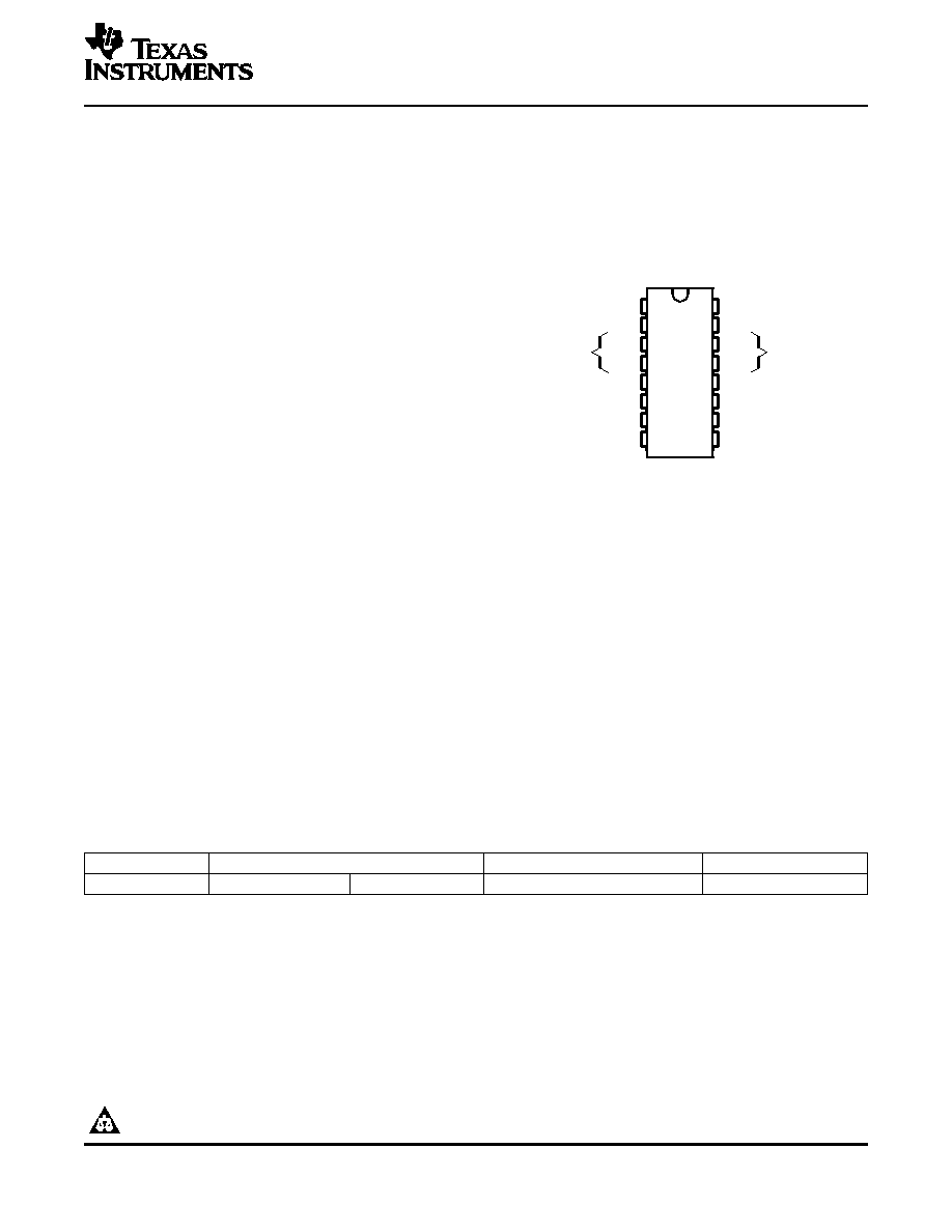
1
2
3
4
5
6
7
8
16
15
14
13
12
11
10
9
CT
RT
Error
1IN +
Amplifier 1
1IN
1FEEDBACK
1DTC
1OUT
GND
REF
SCP
2IN +
Error
2IN
Amplifier 2
2FEEDBACK
2DTC
2OUT
VCC
D PACKAGE
(TOP VIEW)
DESCRIPTION/ORDERING INFORMATION
TL1451A-EP
DUAL PULSE-WIDTH-MODULATION CONTROL CIRCUITS
SLVS614 – DECEMBER 2005
Controlled Baseline
Variable Dead Time Provides Control Over
Total Range
– One Assembly/Test Site, One Fabrication
Site
Internal Regulator Provides a Stable 2.5-V
Reference Supply
Enhanced Diminishing Manufacturing
Sources (DMS) Support
Enhanced Product-Change Notification
Qualification Pedigree (1)
Complete Pulse-Width Modulation (PWM)
Power-Control Circuitry
Completely Synchronized Operation
Internal Undervoltage Lockout Protection
Wide Supply-Voltage Range
Internal Short-Circuit Protection
Oscillator Frequency . . . 500 kHz Max
(1)
Component qualification in accordance with JEDEC and
industry standards to ensure reliable operation over an
extended temperature range. This includes, but is not limited
to, Highly Accelerated Stress Test (HAST) or biased 85/85,
temperature cycle, autoclave or unbiased HAST,
electromigration, bond intermetallic life, and mold compound
life. Such qualification testing should not be viewed as
justifying use of this component beyond specified
performance and environmental limits.
The TL1451A-EP incorporates on a single monolithic chip all the functions required in the construction of two
pulse-width modulation (PWM) control circuits. Designed primarily for power-supply control, the TL1451A-EP
contains an on-chip 2.5-V regulator, two error amplifiers, an adjustable oscillator, two dead-time comparators,
undervoltage lockout circuitry, and dual common-emitter output transistor circuits.
The uncommitted output transistors provide common-emitter output capability for each controller. The internal
amplifiers exhibit a common-mode voltage range from 1.04 V to 1.45 V. The dead-time control (DTC) comparator
has no offset unless externally altered and can provide 0% to 100% dead time. The on-chip oscillator can be
operated by terminating RT and CT. During low VCC conditions, the undervoltage lockout control circuit feature
locks the outputs off until the internal circuitry is operational.
The TL1451A-EP is characterized for operation from –55
°C to 125°C.
ORDERING INFORMATION
TA
PACKAGE(1)
ORDERABLE PART NUMBER
TOP-SIDE MARKING
–55
°C to 125°C
SOIC – D
Tape and reel
TL1451AMDREP
TL1451EPG4
(1)
Package drawings, standard packing quantities, thermal data, symbolization, and PCB design guidelines are available at
www.ti.com/sc/package.
Please be aware that an important notice concerning availability, standard warranty, and use in critical applications of Texas
Instruments semiconductor products and disclaimers thereto appears at the end of this data sheet.
PRODUCTION DATA information is current as of publication date.
Copyright 2005, Texas Instruments Incorporated
Products conform to specifications per the terms of the Texas
On products compliant to MIL-PRF-38535, all parameters are
Instruments standard warranty. Production processing does not
tested unless otherwise noted. On all other products, production
necessarily include testing of all parameters.
processing does not necessarily include testing of all parameters.
相關(guān)PDF資料 |
PDF描述 |
|---|---|
| TL1451G-S16-T | 0.021 A DUAL SWITCHING CONTROLLER, 350 kHz SWITCHING FREQ-MAX, PDSO16 |
| TL1451G-S16-R | 0.021 A DUAL SWITCHING CONTROLLER, 350 kHz SWITCHING FREQ-MAX, PDSO16 |
| TL1454CN | 1 A DUAL SWITCHING CONTROLLER, 2000 kHz SWITCHING FREQ-MAX, PDIP16 |
| TL1454CD | 1 A DUAL SWITCHING CONTROLLER, 2000 kHz SWITCHING FREQ-MAX, PDSO16 |
| TL1454IDR | 1 A DUAL SWITCHING CONTROLLER, 2000 kHz SWITCHING FREQ-MAX, PDSO16 |
相關(guān)代理商/技術(shù)參數(shù) |
參數(shù)描述 |
|---|---|
| TL1451AMFK | 制造商:TI 制造商全稱:Texas Instruments 功能描述:DUAL PULSE-WIDTH-MODULATION CONTROL CIRCUITS |
| TL1451AMFKB | 制造商:Rochester Electronics LLC 功能描述:- Bulk |
| TL1451AMJ | 制造商:Rochester Electronics LLC 功能描述:PWM CONTROLLER, DUAL, VOLTAGE MODE W/DTC - Bulk |
| TL1451AN | 制造商:TI 制造商全稱:Texas Instruments 功能描述:DUAL PULSE-WIDTH-MODULATION CONTROL CIRCUITS |
| TL1451ANS | 制造商:TI 制造商全稱:Texas Instruments 功能描述:DUAL PULSE-WIDTH-MODULATION CONTROL CIRCUITS |
發(fā)布緊急采購,3分鐘左右您將得到回復(fù)。