- 您現(xiàn)在的位置:買賣IC網(wǎng) > PDF目錄68797 > TL598MFKB (TEXAS INSTRUMENTS INC) 0.25 A SWITCHING CONTROLLER, 300 kHz SWITCHING FREQ-MAX, CQCC20 PDF資料下載
參數(shù)資料
| 型號: | TL598MFKB |
| 廠商: | TEXAS INSTRUMENTS INC |
| 元件分類: | 穩(wěn)壓器 |
| 英文描述: | 0.25 A SWITCHING CONTROLLER, 300 kHz SWITCHING FREQ-MAX, CQCC20 |
| 封裝: | CERAMIC, LCC-20 |
| 文件頁數(shù): | 11/17頁 |
| 文件大小: | 598K |
| 代理商: | TL598MFKB |
TL598
PULSEWIDTHMODULATION CONTROL CIRCUITS
SLVS053D FEBRUARY 1988 REVISED NOVEMBER 2003
3
POST OFFICE BOX 655303
DALLAS, TEXAS 75265
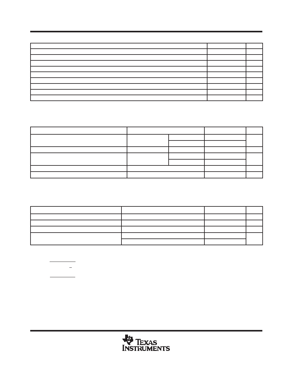
recommended operating conditions
MIN
MAX
UNIT
VCC
Supply voltage
7
40
V
VI
Amplifier input voltage
0
VCC2
V
IO
Collector voltage
40
V
IIL
Output current (each output), sink or source
200
mA
Current into feedback terminal
0.3
mA
CT
Timing capacitor
0.00047
10
F
RT
Timing resistor
1.8
500
k
fosc
Oscillator frequency
1
300
kHz
TA
Operating free-air temperature
0
70
°C
electrical characteristics over recommended operating free-air temperature range, VCC = 15 V
(unless otherwise noted)
reference section (see Note 4)
PARAMETER
TEST CONDITIONS
MIN
TYP
MAX
UNIT
Output voltage (REF)
IO = 1 mA
TA = 25°C
4.95
5
5.05
V
Output voltage (REF)
IO = 1 mA
TA = full range
4.9
5.1
V
Input regulation
VCC = 7 V to 40 V
TA = 25°C
2
25
mV
Output regulation
IO = 1 mA to 10 mA
TA = 25°C
1
15
mV
Output regulation
IO = 1 mA to 10 mA
TA = full range
50
mV
Output voltage change with temperature
TA = MIN to MAX
2
10
mV/V
Short-circuit output current§
REF = 0 V
10
48
mA
Full range is 0°C to 70°C.
All typical values, except for parameter changes with temperature, are at TA = 25°C.
§ Duration of the short circuit should not exceed one second.
NOTE 4: Pulse-testing techniques that maintain the junction temperature as close to the ambient temperature as possible must be used.
oscillator section, CT = 0.001 F, RT = 12 k (see Figure 1) (see Note 4)
PARAMETER
TEST CONDITIONS
MIN
TYP
MAX
UNIT
Frequency
100
kHz
Standard deviation of frequency
All values of VCC, CT, RT, TA constant
100
Hz/kHz
Frequency change with voltage
VCC = 7 V to 40 V,
TA = 25°C
1
10
Hz/kHz
Frequency change with temperature#
TA = full range
70
120
Hz/kHz
Frequency change with temperature#
TA = full range,
CT = 0.01 F
50
80
Hz/kHz
Full range is 0°C to 70°C.
All typical values, except for parameter changes with temperature, are at TA = 25°C.
Standard deviation is a measure of the statistical distribution about the mean, as derived from the formula:
# Effects of temperature on external RT and CT are not taken into account.
NOTE 4. Pulse-testing techniques that maintain the junction temperature as close to the ambient temperature as possible must be used.
s +
N
n
+1
(xn * X)
2
N
* 1
相關PDF資料 |
PDF描述 |
|---|---|
| TL598CDRG4 | 0.25 A SWITCHING CONTROLLER, 300 kHz SWITCHING FREQ-MAX, PDSO16 |
| TL598CD | 0.25 A SWITCHING CONTROLLER, 300 kHz SWITCHING FREQ-MAX, PDSO16 |
| 5962-9167101MXX | 3 A SWITCHING REGULATOR, 58 kHz SWITCHING FREQ-MAX, MBFM2 |
| 5962-9175801MPA | OP-AMP, 3500 uV OFFSET-MAX, 300 MHz BAND WIDTH, CDIP8 |
| 5962-9175802MPA | OP-AMP, 1800 uV OFFSET-MAX, CDIP8 |
相關代理商/技術參數(shù) |
參數(shù)描述 |
|---|---|
| TL598MJB | 制造商:TI 制造商全稱:Texas Instruments 功能描述:PULSE-WIDTH-MODULATION CONTROL CIRCUITS |
| TL598N | 制造商:TI 制造商全稱:Texas Instruments 功能描述:PULSE-WIDTH-MODULATION CONTROL CIRCUITS |
| TL598QD | 制造商:TI 制造商全稱:Texas Instruments 功能描述:PULSE-WIDTH-MODULATION CONTROL CIRCUITS |
| TL598QDR | 制造商:TI 制造商全稱:Texas Instruments 功能描述:PULSE-WIDTH-MODULATION CONTROL CIRCUITS |
| TL598QN | 制造商:TI 制造商全稱:Texas Instruments 功能描述:PULSE-WIDTH-MODULATION CONTROL CIRCUITS |
發(fā)布緊急采購,3分鐘左右您將得到回復。