- 您現(xiàn)在的位置:買賣IC網(wǎng) > PDF目錄385933 > TLS24318 (Texas Instruments, Inc.) Magnetoresistive/Thin-Film Read/Write Preamplifiers(8通道磁阻/薄膜讀/寫用前置放大器) PDF資料下載
參數(shù)資料
| 型號: | TLS24318 |
| 廠商: | Texas Instruments, Inc. |
| 英文描述: | Magnetoresistive/Thin-Film Read/Write Preamplifiers(8通道磁阻/薄膜讀/寫用前置放大器) |
| 中文描述: | 磁阻/薄膜讀/寫前置放大器(8通道磁阻/薄膜讀/寫用前置放大器) |
| 文件頁數(shù): | 9/31頁 |
| 文件大?。?/td> | 676K |
| 代理商: | TLS24318 |
第1頁第2頁第3頁第4頁第5頁第6頁第7頁第8頁當(dāng)前第9頁第10頁第11頁第12頁第13頁第14頁第15頁第16頁第17頁第18頁第19頁第20頁第21頁第22頁第23頁第24頁第25頁第26頁第27頁第28頁第29頁第30頁第31頁
TLS24308, TLS24310, TLS24318, TLS24320
8- AND 10-CHANNEL MAGNETORESISTIVE/THIN-FILM
READ/WRITE PREAMPLIFIERS
SQHS009 – JANUARY 1996
9
POST OFFICE BOX 655303
DALLAS, TEXAS 75265
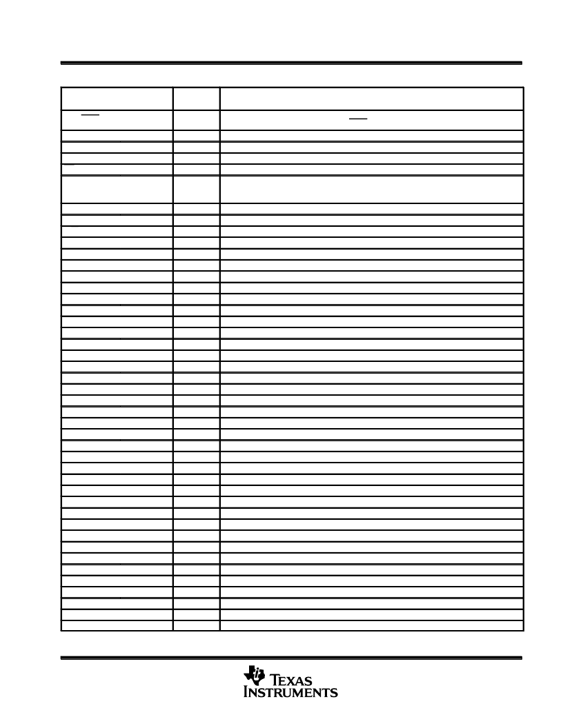
TLS24310 Terminal Functions
TERMINAL
NAME
I/O
DESCRIPTION
NO.
BHV/IBON
10
I/O
Read mode. Buffered-head-voltage (BHV) monitor (amplified by 5
×
).
Write mode. MR-head bias current on (IBON) during write.
Capacitor 1. Decoupling capacitor for MR-bias-current feedback amplifier.
Capacitor 2H. High side of single-to-differential reference decoupling capacitor.
Capacitor 2L. Low side of single-to-differential reference decoupling capacitor.
Chip select. High input selects idle mode.
Fault detection/servo enable. FLT/SE low indicates WDX/WDY frequency low, head short or
open, no write current, thermal asperity detected, or low VCC. When FLT/SE = VCC + 1.2 V,
all servo-write heads are turned on for multiwrite servo mode.
Ground
Head select. Selects up to ten heads. During servo-write mode, selects all heads.
Read/write select. A high-level input selects read mode; a low-level input selects write mode.
X-head connection. MR element positive single-ended input.
X-head connection. MR element positive single-ended input.
X-head connection. MR element positive single-ended input.
X-head connection. MR element positive single-ended input.
X-head connection. MR element positive single-ended input.
X-head connection. MR element positive single-ended input.
X-head connection. MR element positive single-ended input.
X-head connection. MR element positive single-ended input.
X-head connection. MR element positive single-ended input.
X-head connection. MR element positive single-ended input.
Read current set. Used to set the magnitude of the read-current bias.
Read data. Differential read-data outputs.
Supply voltage
X-head connection. TF write-section positive differential output.
Y-head connection. TF write-section negative differential output.
X-head connection. TF write-section positive differential output.
Y-head connection. TF write-section negative differential output.
X-head connection. TF write-section positive differential output.
Y-head connection. TF write-section negative differential output.
X-head connection. TF write-section positive differential output.
Y-head connection. TF write-section negative differential output.
X-head connection. TF write-section positive differential output.
Y-head connection. TF write-section negative differential output.
X-head connection. TF write-section positive differential output.
Y-head connection. TF write-section negative differential output.
X-head connection. TF write-section positive differential output.
Y-head connection. TF write-section negative differential output.
X-head connection. TF write-section positive differential output.
Y-head connection. TF write-section negative differential output.
X-head connection. TF write-section positive differential output.
Y-head connection. TF write-section negative differential output.
X-head connection. TF write-section positive differential output.
Y-head connection. TF write-section negative differential output.
Write-current set. Used to set the magnitude of the write-current bias.
Write data. Psuedo-ECL, positive differential write-data inputs.
CAP1
CAP2H
CAP2L
CS
33
17
18
16
I (CMOS)
FLT/SE
14
I/O
GND
HS0–HS3
R/W
R0X
R1X
R2X
R3X
R4X
R5X
R6X
R7X
R8X
R9X
RCS
RDX, RDY
VCC
W0X
W0Y
W1X
W1Y
W2X
W2Y
W3X
W3Y
W4X
W4Y
W5X
W5Y
W6X
W6Y
W7X
W7Y
W8X
W8Y
W9X
W9Y
WCS
WDX, WDY
11, 35
3, 4, 5, 6
15
34
32
31
30
29
40
39
38
37
36
1
13, 12
9
20
19
22
21
24
23
26
25
28
27
41
42
43
44
45
46
47
48
49
50
2
7, 8
I (CMOS)
I (CMOS)
I
I
I
I
I
I
I
I
I
I
I
O
O
O
O
O
O
O
O
O
O
O
O
O
O
O
O
O
O
O
O
O
I
I (PECL)
相關(guān)PDF資料 |
PDF描述 |
|---|---|
| TLS24320 | Magnetoresistive/Thin-Film Read/Write Preamplifiers(10通道磁阻/薄膜讀/寫用前置放大器) |
| TLSU163 | TLSU163 |
| TLSU163F | TLSU163 |
| TLSU164 | TLSU163 |
| TLSU164F | TLSU163 |
相關(guān)代理商/技術(shù)參數(shù) |
參數(shù)描述 |
|---|---|
| TLS245 | 制造商:Texas Instruments 功能描述: |
| TLS24M554DBT | 制造商:Texas Instruments 功能描述:24M554DBT |
| TLS2501DZQLRG1 | 制造商:Texas Instruments 功能描述: |
| TLS251 | 制造商:未知廠家 制造商全稱:未知廠家 功能描述:TLG251, TLY251, TLO251, TLS251 |
| TLS255K100C1A | 制造商:CORNELL DUBILIER ELECTRONICS 功能描述:Cap Tant Wet 2.5uF 100V 10% (5.56 X 15.45mm) Axial |
發(fā)布緊急采購,3分鐘左右您將得到回復(fù)。