- 您現(xiàn)在的位置:買賣IC網(wǎng) > PDF目錄98264 > TMC1175AN2B20 (FAIRCHILD SEMICONDUCTOR CORP) 1-CH 8-BIT FLASH METHOD ADC, PARALLEL ACCESS, PDIP24 PDF資料下載
參數(shù)資料
| 型號: | TMC1175AN2B20 |
| 廠商: | FAIRCHILD SEMICONDUCTOR CORP |
| 元件分類: | ADC |
| 英文描述: | 1-CH 8-BIT FLASH METHOD ADC, PARALLEL ACCESS, PDIP24 |
| 封裝: | DIP-24 |
| 文件頁數(shù): | 5/20頁 |
| 文件大?。?/td> | 427K |
| 代理商: | TMC1175AN2B20 |
PRODUCT SPECIFICATION
TMC1175A
REV. 1.3.3 2/28/02
13
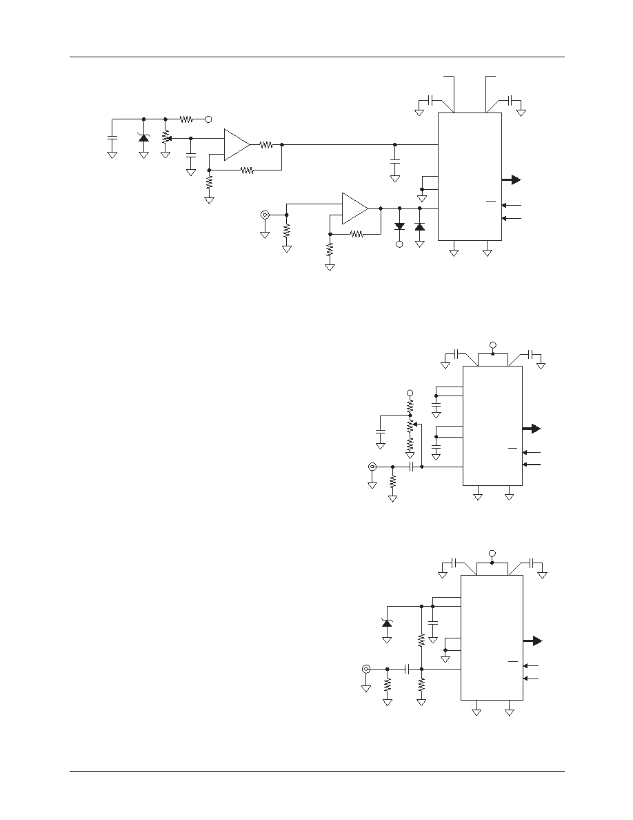
Figure 12. Typical Interface Circuit-High Performance
+5V
+
-
+
-
0.1
F
2V
0.1mF
0.1
F
VDDA
VDDD
VR+
RT
RB
VR-
VIN
AGND
DGND
OE
CONV
D7-0
TMC1175A
0.1
F
0.1
F
2k
1k
LM385
1k
1k
75
455
455
20
Video
Input
+5V
Regulated +5V
Gain Adjust
+5V
27056A
Wideband
Op-amp
Figure 13. Typical Interface Circuit – Low Cost
Figure 14. Typical Interface Circuit – Stabilized Reference
0.1
F
0.1
F
0.1
F
10
F
+5V
2.2k
2k
560
75
Video
Input
24458A
Offset
Adjust
+5V
0.1
F
0.1
F
VDDA
VDDD
VR+
RT
RB
VR-
VIN
AGND
DGND
OE
CONV
D7-0
TMC1175A
0.1
F
10
F
1k
1k
56
RF
Input
24457A
+5V
0.1
F
0.1
F
VDDA
VDDD
VR+
RT
RB
VR-
VIN
AGND
DGND
OE
CONV
D7-0
TMC1175A
LM385
Grounding
The TMC1175A has separate analog and digital
circuits. To keep digital system noise from the A/D
converter, it is recommended that power supply voltages
(VDDD and VDDA) originate from separate sources with
VDDA regulated, and that ground connections (DGND and
AGND) be made to the analog ground plane. Power supply
pins should be individually decoupled at the pin. The digital
circuitry that gets its input from the TMC1175A should be
referred to the system digital ground plane.
Printed Circuit Board Layout
Designing with high performance mixed-signal circuits
demands printed circuits with ground planes. Wire-wrap is
not an option, even for breadboarding. Overall system per-
formance is strongly inuenced by the board layout. Capac-
itive coupling from digital to analog circuits may result in
poor A/D conversion. Consider the following suggestions
when doing the layout:
1.
Keep the critical analog traces (VIN, RT, RB, VR+,
VR-) as short as possible and as far as possible from all
digital signals. The TMC1175A should be located near
the board edge, close to the analog input connectors.
2.
The power plane for the TMC1175A should be sepa-
rate from that which supplies the rest of the digital cir-
cuitry. A single power plane should be used for all of
the VDD pins. If the power supply for the TMC1175A
is the same as that of the system's digital circuitry,
power to the TMC1175A should be decoupled with
ferrite beads and 0.1F capacitors to reduce noise.
3.
The ground plane should be solid, not cross-hatched.
Connections to the ground plane should have very
short leads.
相關(guān)PDF資料 |
PDF描述 |
|---|---|
| TMC1175AN2B30 | 1-CH 8-BIT FLASH METHOD ADC, PARALLEL ACCESS, PDIP24 |
| TMC1175AN2C50 | 1-CH 8-BIT FLASH METHOD ADC, PARALLEL ACCESS, PDIP24 |
| TMC1175AM7C50 | 1-CH 8-BIT FLASH METHOD ADC, PARALLEL ACCESS, PDSO24 |
| TMC1175AR3C50 | 1-CH 8-BIT FLASH METHOD ADC, PARALLEL ACCESS, PQCC28 |
| TMC1175B2F20 | 8-BIT CONVERTER SUBSYSTEM ADC, PARALLEL ACCESS, CDIP24 |
相關(guān)代理商/技術(shù)參數(shù) |
參數(shù)描述 |
|---|---|
| TMC1175AN2C20 | 制造商:FAIRCHILD 制造商全稱:Fairchild Semiconductor 功能描述:Video A/D Conveter |
| TMC1175AN2C30 | 制造商:FAIRCHILD 制造商全稱:Fairchild Semiconductor 功能描述:Video A/D Conveter |
| TMC1175AN2C40 | 制造商:Rochester Electronics LLC 功能描述:- Bulk |
| TMC1175AN2C50 | 制造商:Rochester Electronics LLC 功能描述:- Bulk |
| TMC1175AR3B20 | 制造商:Rochester Electronics LLC 功能描述:- Bulk |
發(fā)布緊急采購,3分鐘左右您將得到回復(fù)。