- 您現(xiàn)在的位置:買賣IC網(wǎng) > PDF目錄98274 > TPA5050RSAR (TEXAS INSTRUMENTS INC) SPECIALTY CONSUMER CIRCUIT, PQCC16 PDF資料下載
參數(shù)資料
| 型號(hào): | TPA5050RSAR |
| 廠商: | TEXAS INSTRUMENTS INC |
| 元件分類: | 消費(fèi)家電 |
| 英文描述: | SPECIALTY CONSUMER CIRCUIT, PQCC16 |
| 封裝: | 4 X 4 MM, GREEN, PLASTIC, QFN-16 |
| 文件頁(yè)數(shù): | 3/21頁(yè) |
| 文件大小: | 784K |
| 代理商: | TPA5050RSAR |
第1頁(yè)第2頁(yè)當(dāng)前第3頁(yè)第4頁(yè)第5頁(yè)第6頁(yè)第7頁(yè)第8頁(yè)第9頁(yè)第10頁(yè)第11頁(yè)第12頁(yè)第13頁(yè)第14頁(yè)第15頁(yè)第16頁(yè)第17頁(yè)第18頁(yè)第19頁(yè)第20頁(yè)第21頁(yè)
www.ti.com
RJ PACKET LENGTH REGISTERS (0x07)
COMPLETE UPDATE REGISTER (0x08)
SLOS492B – MAY 2006 – REVISED MAY 2007
If the result of the formula above is greater than the maximum number of delay samples (8191 for TPA5050),
then the value is limited to this maximum before passing to the delay block.
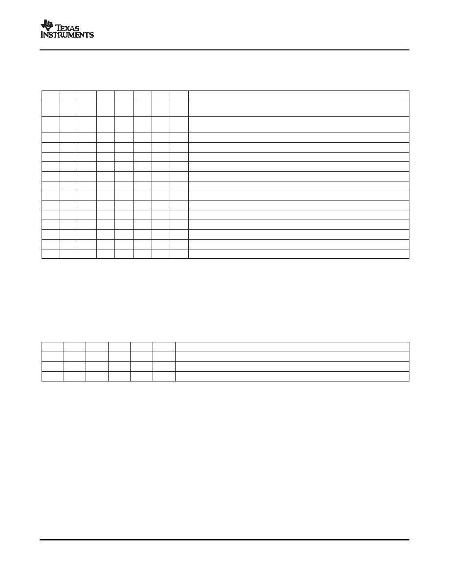
Table 5. Frame Delay Registers (0x06)(1)
D7
D6
D5
D4
D3
D2
D1
D0
FUNCTION
0
Settings in this register are masked and audio delay is determined by
settings in the right/left audio delay registers.
1
Right/left audio delay registers are masked and delay is determined by settings in
this register.
0
Frame rate = 50 Hz
1
Frame rate = 59.94 Hz
0
Audio sample rate = 32 kHz
0
1
Audio sample rate = 44.1 kHz
0
1
0
Audio sample rate = 48 kHz
0
1
Audio sample rate = 88.2 kHz
1
0
Audio sample rate = 96 kHz
1
0
1
Audio sample rate = 176.4 kHz
1
0
Audio sample rate = 192 kHz
1
Audio sample rate = 192 kHz
0
Delay frames = 1
0
1
Delay frames = 2
1
Delay frames = 8
(1)
Default values are in bold.
This register is only used in right justified mode. The decimal value of bits [5:0] represents the width of the
useable data in a right justified audio stream. The number of BCLK transitions between LRCLK transitions must
be greater than or equal to the packet length selected in this register. The maximum packet length value is 24
bits. Any setting greater whose numerical value is greater than 24 bits is limited to the maximum 24 bits.
Table 6. RJ Package Length (0x07)(1)
D5
D4
D3
D2
D1
D0
FUNCTION
0
Packet length = 0 bits
0
1
Packet length = 1 bits
0
1
X
Packet length = 24 bits
(1)
Default values are in bold.
Since the audio delay values are divided among several registers, it is likely that multiple writes would be
necessary to configure the device. This may cause interruptions in the audio stream and unwanted pops and
clicks might occur as register data is passed to delay functional block.
To avoid this from happening, the Complete Update register is used to transfer the user settings from the
register file to the delay functional block when a 1 is written to the LSB. For example, if the right delay is set to
35 samples, and the left delay is set to 300 samples, the device holds the right channel in MUTE until 35
samples of audio data have passed, and holds the left channel in MUTE until 300 samples of audio data have
passed.
Note that the individual channels can be muted using the upper bits of the Control Registers without writing to
the Complete Update registers.
11
相關(guān)PDF資料 |
PDF描述 |
|---|---|
| TPA5050RSATG4 | SPECIALTY CONSUMER CIRCUIT, PQCC16 |
| TPA5050RSAT | SPECIALTY CONSUMER CIRCUIT, PQCC16 |
| TPA5051RSARG4 | SPECIALTY CONSUMER CIRCUIT, PQCC16 |
| TPA5051RSAR | SPECIALTY CONSUMER CIRCUIT, PQCC16 |
| TPA5051RSATG4 | SPECIALTY CONSUMER CIRCUIT, PQCC16 |
相關(guān)代理商/技術(shù)參數(shù) |
參數(shù)描述 |
|---|---|
| TPA5050RSARG4 | 功能描述:音頻 DSP St Dig Aud Delay Proc RoHS:否 制造商:Texas Instruments 工作電源電壓: 電源電流: 工作溫度范圍: 安裝風(fēng)格: 封裝 / 箱體: 封裝:Tube |
| TPA5050RSAT | 功能描述:音頻 DSP St Dig Aud Delay Proc RoHS:否 制造商:Texas Instruments 工作電源電壓: 電源電流: 工作溫度范圍: 安裝風(fēng)格: 封裝 / 箱體: 封裝:Tube |
| TPA5050RSATG4 | 功能描述:音頻 DSP St Dig Aud Delay Proc RoHS:否 制造商:Texas Instruments 工作電源電壓: 電源電流: 工作溫度范圍: 安裝風(fēng)格: 封裝 / 箱體: 封裝:Tube |
| TPA5051 | 制造商:TI 制造商全稱:Texas Instruments 功能描述:FOUR CHANNEL DIGITAL AUDIO LIP-SYNC DELAY WITH I2C CONTROL |
| TPA5051_07 | 制造商:TI 制造商全稱:Texas Instruments 功能描述:FOUR CHANNEL DIGITAL AUDIO LIP-SYNC DELAY WITH I2C CONTROL |
發(fā)布緊急采購(gòu),3分鐘左右您將得到回復(fù)。