- 您現(xiàn)在的位置:買賣IC網(wǎng) > PDF目錄98274 > TPA6040A4RHBT (TEXAS INSTRUMENTS INC) 2.3 W, 2 CHANNEL, AUDIO AMPLIFIER, PQCC32 PDF資料下載
參數(shù)資料
| 型號(hào): | TPA6040A4RHBT |
| 廠商: | TEXAS INSTRUMENTS INC |
| 元件分類: | 音頻/視頻放大 |
| 英文描述: | 2.3 W, 2 CHANNEL, AUDIO AMPLIFIER, PQCC32 |
| 封裝: | GREEN, PLASTIC, QFN-32 |
| 文件頁(yè)數(shù): | 11/28頁(yè) |
| 文件大小: | 685K |
| 代理商: | TPA6040A4RHBT |
第1頁(yè)第2頁(yè)第3頁(yè)第4頁(yè)第5頁(yè)第6頁(yè)第7頁(yè)第8頁(yè)第9頁(yè)第10頁(yè)當(dāng)前第11頁(yè)第12頁(yè)第13頁(yè)第14頁(yè)第15頁(yè)第16頁(yè)第17頁(yè)第18頁(yè)第19頁(yè)第20頁(yè)第21頁(yè)第22頁(yè)第23頁(yè)第24頁(yè)第25頁(yè)第26頁(yè)第27頁(yè)第28頁(yè)
www.ti.com
R
L
C
V
O(PP)
V
O(PP)
V
DD
–3dB
f
c
Headphone Amplifier Description
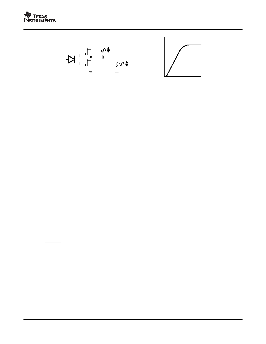
fc +
1
2pR
LCO
(4)
C
O +
1
2pR
Lfc
(5)
SLOS519A – APRIL 2007 – REVISED APRIL 2007
Figure 35. Single-Ended Configuration and Frequency Response
Bridge-tying the outputs in a typical computer audio, LCD TV, or multimedia LCD monitor application drastically
increases output power. For example, if an amplifier in a single-ended configuration was capable of outputting a
maximum of 250 mW for a given load with a supply voltage of 12 V, then that same amplifier would be able to
output 1 W of power in a BTL configuration with the same supply voltage and load. In addition to the increase in
output power, the BTL configuration does not suffer from the same low-frequency issues that plague the
single-ended configuration. In a BTL configuration, there is no need for an output capacitor to block dc, so no
unwanted filtering occurs. In addition, the BTL configuration saves money and space, as the dc-blocking
capacitors needed for single-ended operation are large and expensive. For example, with an 8-
load in SE
operation, the user needs a 1000-
F capacitor to obtain a cutoff frequency below 20 Hz. This capacitor is
expensive and large.
The headphone amplifier has a fixed gain of -1.5 V/V. It uses single-ended (SE) inputs. The DirectPath
amplifier architecture operates from a single supply but makes use of an internal charge pump to provide a
negative voltage rail. Combining the user-provided positive rail and the negative rail generated by the IC, the
device operates in what is effectively a split supply mode. The output voltages are now centered at zero volts
with the capability to swing to the positive rail or negative rail. The DirectPath amplifier requires no output dc
blocking capacitors and does not place any voltage on the sleeve. The block diagram and waveform of
Figure 36 illustrate the ground-referenced headphone architecture. This is the architecture of the TPA6040A4.
Single-supply headphone amplifiers typically require dc-blocking capacitors. The capacitors are required
because most headphone amplifiers have a dc bias on the outputs pin. If the dc bias is not removed, the output
signal is severely clipped, and large amounts of dc current rush through the headphones, potentially damaging
them. The left-side drawing in Figure 36 illustrates the conventional headphone amplifier connection to the
headphone jack and output signal.
DC blocking capacitors are often large in value. The headphone speakers (typical resistive values of 16
or
32
) combine with the dc blocking capacitors to form a high-pass filter. Equation 4 shows the relationship
between the load impedance (RL), the capacitor (CO), and the cutoff frequency (fC).
If fc is low, the capacitor must then have a large value because the load resistance is small. Large capacitance
values require large package sizes. Large package sizes consume PCB area, stand high above the PCB,
increase cost of assembly, and can reduce the fidelity of the audio output signal.
Two different headphone amplifier applications are available that allow for the removal of the output dc blocking
capacitors. The capacitor-less amplifier architecture is implemented in the same manner as the conventional
amplifier with the exception of the headphone jack shield pin. This amplifier provides a reference voltage, which
19
相關(guān)PDF資料 |
PDF描述 |
|---|---|
| TPA6041A4RHBRG4 | 2.6 W, 2 CHANNEL, AUDIO AMPLIFIER, PQCC32 |
| TPA6041A4RHBR | 2.6 W, 2 CHANNEL, AUDIO AMPLIFIER, PQCC32 |
| TPA6043A4RHBRG4 | 2.3 W, 2 CHANNEL, AUDIO AMPLIFIER, PQCC32 |
| TPA6043A4RHBR | 2.3 W, 2 CHANNEL, AUDIO AMPLIFIER, PQCC32 |
| TPA6043A4RHB | 2.3 W, 2 CHANNEL, AUDIO AMPLIFIER, PQCC32 |
相關(guān)代理商/技術(shù)參數(shù) |
參數(shù)描述 |
|---|---|
| TPA6041A4 | 制造商:TI 制造商全稱:Texas Instruments 功能描述:2-W STEREO AUDIO POWER AMPLIFIER WITH DirectPath? STEREO HEADPHONE DRIVE AND REGULATOR |
| TPA6041A4RHBR | 功能描述:音頻放大器 2W St Aud Pwr Amp RoHS:否 制造商:STMicroelectronics 產(chǎn)品:General Purpose Audio Amplifiers 輸出類型:Digital 輸出功率: THD + 噪聲: 工作電源電壓:3.3 V 電源電流: 最大功率耗散: 最大工作溫度: 安裝風(fēng)格:SMD/SMT 封裝 / 箱體:TQFP-64 封裝:Reel |
| TPA6041A4RHBRG4 | 功能描述:音頻放大器 2W St Aud Pwr Amp RoHS:否 制造商:STMicroelectronics 產(chǎn)品:General Purpose Audio Amplifiers 輸出類型:Digital 輸出功率: THD + 噪聲: 工作電源電壓:3.3 V 電源電流: 最大功率耗散: 最大工作溫度: 安裝風(fēng)格:SMD/SMT 封裝 / 箱體:TQFP-64 封裝:Reel |
| TPA6043A4 | 制造商:TI 制造商全稱:Texas Instruments 功能描述:2-W STEREO AUDIO POWER AMPLIFIER WITH DirectPath? STEREO HEADPHONE DRIVE AND REGULATOR |
| TPA6043A4RHB | 制造商:TI 制造商全稱:Texas Instruments 功能描述:2-W STEREO AUDIO POWER AMPLIFIER WITH DirectPath⑩ STEREO HEADPHONE DRIVE AND REGULATOR |
發(fā)布緊急采購(gòu),3分鐘左右您將得到回復(fù)。