- 您現(xiàn)在的位置:買賣IC網(wǎng) > PDF目錄98284 > TPS62601YFFT (TEXAS INSTRUMENTS INC) 1.1 A SWITCHING REGULATOR, 6600 kHz SWITCHING FREQ-MAX, BGA6 PDF資料下載
參數(shù)資料
| 型號: | TPS62601YFFT |
| 廠商: | TEXAS INSTRUMENTS INC |
| 元件分類: | 穩(wěn)壓器 |
| 英文描述: | 1.1 A SWITCHING REGULATOR, 6600 kHz SWITCHING FREQ-MAX, BGA6 |
| 封裝: | GREEN, DSBGA-6 |
| 文件頁數(shù): | 12/24頁 |
| 文件大小: | 785K |
| 代理商: | TPS62601YFFT |
ABSOLUTE MAXIMUM RATINGS
DISSIPATION RATINGS
(1)
SLVS678 – JUNE 2008 ...................................................................................................................................................................................................... www.ti.com
These devices have limited built-in ESD protection. The leads should be shorted together or the device placed in conductive foam
during storage or handling to prevent electrostatic damage to the MOS gates.
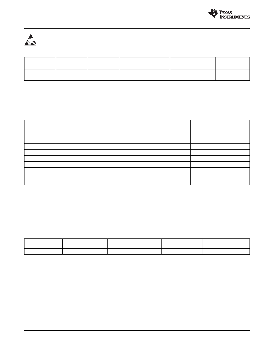
ORDERING INFORMATION(1)
PACKAGE
PART
OUTPUT
PACKAGE
ORDERING(2)(3)
MARKING
NUMBER
VOLTAGE
CHIP CODE
TPS62600
1.83V
TPS62600YFF
G9
-40°C to 85°C
YFF-6
TPS62601
1.8V
TPS62601YFF
GA
(1)
For the most current package and ordering information, see the Package Option Addendum at the end of this document, or see the TI
website at www.ti.com.
(2)
The YFF package is available in tape and reel. Add a R suffix (TPS62600YFFR) to order quantities of 3000 parts. Add a T suffix
(TPS62600YFFT) to order quantities of 250 parts.
(3)
Internal tap points are available to facilitate output voltages in 25mV increments.
over operating free-air temperature range (unless otherwise noted)
(1)
UNIT
Voltage at VIN, SW(2)
-0.3 V to 7 V
VI
Voltage at FB(2)
-0.3 V to 3.6 V
Voltage at EN, MODE (2)
-0.3 V to VI + 0.3 V
Power dissipation
Internally limited
TA
Operating temperature range(3)
-40°C to 85°C
TJ (max)
Maximum operating junction temperature
150°C
Tstg
Storage temperature range
-65°C to 150°C
Human body model
2 kV
ESD rating (4)
Charge device model
1 kV
Machine model
200 V
(1)
Stresses beyond those listed under absolute maximum ratings may cause permanent damage to the device. These are stress ratings
only and functional operation of the device at these or any other conditions beyond those indicated under recommended operating
conditions is not implied. Exposure to absolute-maximum-rated conditions for extended periods may affect device reliability.
(2)
All voltage values are with respect to network ground terminal.
(3)
In applications where high power dissipation and/or poor package thermal resistance is present, the maximum ambient temperature may
have to be derated. Maximum ambient temperature (TA(max)) is dependent on the maximum operating junction temperature (TJ(max)), the
maximum power dissipation of the device in the application (PD(max)), and the junction-to-ambient thermal resistance of the part/package
in the application (
θ
JA), as given by the following equation: TA(max)= TJ(max)–(θJA X PD(max)).
(4)
The human body model is a 100-pF capacitor discharged through a 1.5-k
resistor into each pin. The machine model is a 200-pF
capacitor discharged directly into each pin.
POWER RATING
DERATING FACTOR
PACKAGE
RθJA
(2)
RθJB
(2)
TA ≤ 25°C
ABOVE TA = 25°C
YFF-6
125°C/W
53°C/W
800mW
8mW/°C
(1)
Maximum power dissipation is a function of TJ(max), θJA and TA. The maximum allowable power dissipation at any allowable ambient
temperature is PD = [TJ(max)-TA] / θJA.
(2)
This thermal data is measured with high-K board (4 layers board according to JESD51-7 JEDEC standard).
2
Copyright 2008, Texas Instruments Incorporated
相關(guān)PDF資料 |
PDF描述 |
|---|---|
| TPS62660YFF | 1.75 A SWITCHING REGULATOR, 6600 kHz SWITCHING FREQ-MAX, BGA6 |
| TPS62671YFDR | 1.15 A SWITCHING REGULATOR, 6600 kHz SWITCHING FREQ-MAX, PBGA6 |
| TPS62675YFDR | 1.25 A SWITCHING REGULATOR, 6600 kHz SWITCHING FREQ-MAX, PBGA6 |
| TPS62675YFDT | 1.25 A SWITCHING REGULATOR, 6600 kHz SWITCHING FREQ-MAX, PBGA6 |
| TPS62679ZYFMR | 1.15 A SWITCHING REGULATOR, 6000 kHz SWITCHING FREQ-MAX, PBGA6 |
相關(guān)代理商/技術(shù)參數(shù) |
參數(shù)描述 |
|---|---|
| TPS62611YFDR | 制造商:Texas Instruments 功能描述:6MHZ SYNC BUCK, 1.8V, LOW IOUT, NO BSC 制造商:Texas Instruments 功能描述:6Mhz buck converter, 1.8V, 300mA |
| TPS62611YFDT | 制造商:Texas Instruments 功能描述: |
| TPS62612YFDR | 功能描述:直流/直流開關(guān)轉(zhuǎn)換器 350mA,6MHz,1.5Vout Hi Eff RoHS:否 制造商:STMicroelectronics 最大輸入電壓:4.5 V 開關(guān)頻率:1.5 MHz 輸出電壓:4.6 V 輸出電流:250 mA 輸出端數(shù)量:2 最大工作溫度:+ 85 C 安裝風格:SMD/SMT |
| TPS62612YFDT | 功能描述:直流/直流開關(guān)轉(zhuǎn)換器 350mA,6MHz,1.5Vout Hi Eff RoHS:否 制造商:STMicroelectronics 最大輸入電壓:4.5 V 開關(guān)頻率:1.5 MHz 輸出電壓:4.6 V 輸出電流:250 mA 輸出端數(shù)量:2 最大工作溫度:+ 85 C 安裝風格:SMD/SMT |
| TPS62615EVM-419 | 功能描述:電源管理IC開發(fā)工具 TPS62615 Eval Mod RoHS:否 制造商:Maxim Integrated 產(chǎn)品:Evaluation Kits 類型:Battery Management 工具用于評估:MAX17710GB 輸入電壓: 輸出電壓:1.8 V |
發(fā)布緊急采購,3分鐘左右您將得到回復。