- 您現(xiàn)在的位置:買賣IC網 > PDF目錄225341 > TRF2056PWR (TEXAS INSTRUMENTS INC) PLL FREQUENCY SYNTHESIZER, 1200 MHz, PDSO20 PDF資料下載
參數資料
| 型號: | TRF2056PWR |
| 廠商: | TEXAS INSTRUMENTS INC |
| 元件分類: | PLL合成/DDS/VCOs |
| 英文描述: | PLL FREQUENCY SYNTHESIZER, 1200 MHz, PDSO20 |
| 封裝: | PLASTIC, SOP-20 |
| 文件頁數: | 13/24頁 |
| 文件大小: | 327K |
| 代理商: | TRF2056PWR |
TRF2056
LOW VOLTAGE 1.2GHz FRACTIONALN/INTEGERN SYNTHESIZER
SLWS111– NOVEMBER 2000
20
POST OFFICE BOX 655303
DALLAS, TEXAS 75265
PRINCIPLES OF OPERATION
reference divider
The input signal on REFIN is amplified by a single-ended, ac-coupled input buffer/amplifier that has sufficient
sensitivity (300 mVpp at 50 MHz) for direct connection to a typical TCXO. The 12-bit (NR) reference divider total
division ratio can be expressed as:
NTotal = NR
where NR = 4 to 4095.
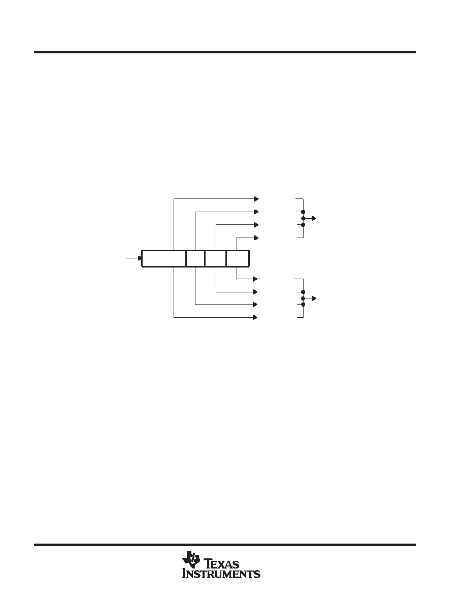
A four-section postscaler is connected to the output of the reference divider section. The main and auxiliary
synthesizer sections can individually select a reference postscaler division of 1, 2, 4, or 8 by programming fields
SM and SA, respectively (see Figure 9).
Divide by NR
÷ 2
SM = 11
SM = 10
SM = 01
SM = 00
SA = 11
SA = 10
SA = 01
SA = 00
MAIN SELECT
AUXILIARY SELECT
Main Phase
Detector
Auxiliary
Phase Detector
Reference Input
Figure 9. Reference Divider
phase detectors
The main and auxiliary synthesizer sections (see Figure 10) incorporate dual D-type flip-flop phase-frequency
detectors (PFD). A PFD has gain with a phase error over a range of
±2π and exhibits an infinite pull-in range.
Dead-band compensation about zero-phase error is provided by forcing the sourcing and sinking charge pumps
to have a minimum on-time of 1/fRef when the loop is operating in a locked condition.
The phase detectors can be programmed for polarity sense. Normally, external system VCOs have a positive
slope control-voltage frequency characteristic. Some VCOs have a negative slope characteristic. The TRF2056
main and auxiliary phase detectors can be programmed for use with positive or negative slope VCOs using the
MCP and ACP fields, respectively, in the B-Word (EPM mode).
For positive slope VCOs: MCP = ACP = 0
For negative slope VCOs: MCP = ACP = 1
相關PDF資料 |
PDF描述 |
|---|---|
| TRF4000 | Pcs RX-mixer |
| TRF4002PWP | 1850 MHz - 1910 MHz RF/MICROWAVE NARROW BAND MEDIUM POWER AMPLIFIER |
| TRS-1300-1305-8310 | TRIPLE COLOR LED ARRAY |
| TRS-1300-1311-8310 | DUAL COLOR LED ARRAY |
| TRS-1300-1313-1315 | TRIPLE COLOR LED ARRAY |
相關代理商/技術參數 |
參數描述 |
|---|---|
| TRF2253PWR | 制造商:Texas Instruments 功能描述: |
| TRF2253RGL | 制造商:Texas Instruments 功能描述: |
| TRF2253RGLR | 制造商:Texas Instruments 功能描述: |
| TRF2432 | 制造商:TI 制造商全稱:Texas Instruments 功能描述:Dual-Band IQ/IF TRANSCEIVER WITH DUAL VCO SYNTHESIZERS |
| TRF2432_07 | 制造商:TI 制造商全稱:Texas Instruments 功能描述:Dual-Band IQ/IF TRANSCEIVER WITH DUAL VCO SYNTHESIZERS |
發(fā)布緊急采購,3分鐘左右您將得到回復。