- 您現(xiàn)在的位置:買賣IC網(wǎng) > PDF目錄373737 > TSL14S (TAOS Inc.) LIGHT-TO-VOLTAGE CONVERTERS PDF資料下載
參數(shù)資料
| 型號: | TSL14S |
| 廠商: | TAOS Inc. |
| 英文描述: | LIGHT-TO-VOLTAGE CONVERTERS |
| 中文描述: | 光到電壓轉(zhuǎn)換器 |
| 文件頁數(shù): | 2/12頁 |
| 文件大?。?/td> | 197K |
| 代理商: | TSL14S |
TSL12S, TSL13S, TSL14S
LIGHT-TO-VOLTAGE CONVERTERS
TAOS051E
SEPTEMBER 2007
2
Copyright 2007, TAOS Inc.
The
LUMENOLOGY
Company
www.taosinc.com
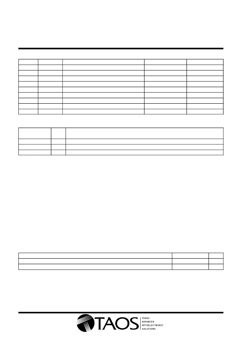
Available Options
DEVICE
TSL12S
TSL12S
TSL12S
TSL13S
TSL13S
TSL13S
TSL14S
TSL14S
TSL14S
T
A
PACKAGE
LEADS
PACKAGE DESIGNATOR
S
S
SM
S
S
SM
S
S
SM
ORDERING NUMBER
TSL12S
TSL12S
LF
TSL12SM
LF
TSL13S
TSL13S
LF
TSL13SM
LF
TSL14S
TSL14S
LF
TSL14SM
LF
0
°
C to 70
°
C
0
°
C to 70
°
C
0
°
C to 70
°
C
0
°
C to 70
°
C
0
°
C to 70
°
C
0
°
C to 70
°
C
0
°
C to 70
°
C
0
°
C to 70
°
C
0
°
C to 70
°
C
3-lead Sidelooker
3-lead Sidelooker — Lead (Pb) Free
3-lead Surface-Mount Sidelooker — Lead (Pb) Free
3-lead Sidelooker
3-lead Sidelooker — Lead (Pb) Free
3-lead Surface-Mount Sidelooker — Lead (Pb) Free
3-lead Sidelooker
3-lead Sidelooker — Lead (Pb) Free
3-lead Surface-Mount Sidelooker — Lead (Pb) Free
Terminal Functions
TERMINAL
NAME
GND
OUT
V
DD
TYPE
DESCRIPTION
NO.
1
3
2
Power supply ground (substrate). All voltages are referenced to GND.
Output voltage.
Supply voltage.
O
Absolute Maximum Ratings over operating free-air temperature range (unless otherwise noted)
Supply voltage, V
DD
(see Note 1)
Output current, I
O
Duration of short-circuit current at (or below) 25
°
C (see Note 2)
Operating free-air temperature range, T
A
Storage temperature range, T
stg
Lead temperature 1,6 mm (1/16 inch) from case for 10 seconds (S Package)
Reflow solder, in accordance with J-STD-020C or J-STD-020D (SM Package)
6 V
. . . . . . . . . . . . . . . . . . . . . . . . . . . . . . . . . . . . . . . . . . . . . . . . . . . . . . . . . . . . .
. . . . . . . . . . . . . . . . . . . . . . . . . . . . . . . . . . . . . . . . . . . . . . . . . . . . . . . . . . . . . . . . . . . . . .
±
10 mA
5 s
. . . . . . . . . . . . . . . . . . . . . . . . . . . . . . . . . . .
25
°
C to 85
°
C
25
°
C to 85
°
C
. . . . . . . . . . . . . . . . . . . . . . . . . . . . . . . . . . . . . . . . . . . .
. . . . . . . . . . . . . . . . . . . . . . . . . . . . . . . . . . . . . . . . . . . . . . . . . . . .
260
°
C
260
°
C
. . . . . . . . . . . . . . . . . . . .
. . . . . . . . . . . . . . . . . . .
Stresses beyond those listed under “absolute maximum ratings” may cause permanent damage to the device. These are stress ratings only, and
functional operation of the device at these or any other conditions beyond those indicated under “recommended operating conditions” is not
implied. Exposure to absolute-maximum-rated conditions for extended periods may affect device reliability.
NOTES:
1. All voltages are with respect to GND.
2. Output may be shorted to supply.
Recommended Operating Conditions
MIN
2.7
NOM
MAX
5.5
UNIT
V
°
C
Supply voltage, V
DD
Operating free-air temperature, T
A
0
70
相關(guān)PDF資料 |
PDF描述 |
|---|---|
| TSL14S-LF | LIGHT-TO-VOLTAGE CONVERTERS |
| TSL14SM-LF | LIGHT-TO-VOLTAGE CONVERTERS |
| TSL12T | LIGHT-TO-VOLTAGE CONVERTERS |
| TSL13 | LIGHT-TO-VOLTAGE CONVERTERS |
| TSL13T | LIGHT-TO-VOLTAGE CONVERTERS |
相關(guān)代理商/技術(shù)參數(shù) |
參數(shù)描述 |
|---|---|
| TSL14S-LF | 功能描述:光頻率和光電壓 Light to Voltage Converter RoHS:否 制造商:ams 峰值波長:1000 nm 工作電源電壓:5 V 最大工作溫度:+ 85 C 最小工作溫度:- 25 C 安裝風(fēng)格: 封裝 / 箱體: |
| TSL14SM-LF | 功能描述:光頻率和光電壓 Light to Voltage Converter RoHS:否 制造商:ams 峰值波長:1000 nm 工作電源電壓:5 V 最大工作溫度:+ 85 C 最小工作溫度:- 25 C 安裝風(fēng)格: 封裝 / 箱體: |
| TSL1LTE12L1F | 功能描述:電流傳感電阻器 - SMD 1watt 0.0121ohm 1% RoHS:否 制造商:Vishay/Dale 電阻:10 mOhms 功率額定值:1 W 容差:1 % 外殼代碼 - in:2512 外殼代碼 - mm:6432 溫度系數(shù):75 PPM / C 系列:WSL 工作溫度范圍:- 65 C to + 170 C 產(chǎn)品:Power Metal Strip Resistors Low Value |
| TSL1LTE15L0F | 制造商:KOA Speer Electronics Inc 功能描述: |
| TSL1LTE16L2F | 功能描述:電流傳感電阻器 - SMD 1watt 0.0162ohm 1% RoHS:否 制造商:Vishay/Dale 電阻:10 mOhms 功率額定值:1 W 容差:1 % 外殼代碼 - in:2512 外殼代碼 - mm:6432 溫度系數(shù):75 PPM / C 系列:WSL 工作溫度范圍:- 65 C to + 170 C 產(chǎn)品:Power Metal Strip Resistors Low Value |
發(fā)布緊急采購,3分鐘左右您將得到回復(fù)。