- 您現(xiàn)在的位置:買賣IC網(wǎng) > PDF目錄365990 > TSPC750AVGSU12LE Microprocessor PDF資料下載
參數(shù)資料
| 型號: | TSPC750AVGSU12LE |
| 英文描述: | Microprocessor |
| 中文描述: | 微處理器 |
| 文件頁數(shù): | 16/44頁 |
| 文件大小: | 870K |
| 代理商: | TSPC750AVGSU12LE |
第1頁第2頁第3頁第4頁第5頁第6頁第7頁第8頁第9頁第10頁第11頁第12頁第13頁第14頁第15頁當(dāng)前第16頁第17頁第18頁第19頁第20頁第21頁第22頁第23頁第24頁第25頁第26頁第27頁第28頁第29頁第30頁第31頁第32頁第33頁第34頁第35頁第36頁第37頁第38頁第39頁第40頁第41頁第42頁第43頁第44頁

16
TSPC750A/740A
2128A–HIREL–01/02
Notes:
1. Thetemperatureisthejunctiontemperatureofthedie.Thethermalassistunit’srawoutputdoesnotindicateanabsolute
temperature,butitmustbeinterpretedbysoftwaretoderivetheabsolutejunctiontemperature.Forinformationaboutthe
useandcalibrationoftheTAU,seetheMotorolaapplicationnoteAN1800/D“programmingthethermalAssistUnitinthe
MPC750AMicroprocessor.Thisspecificationreflectsthetemperaturespansupportedbydesign.
2. ThecomparatorsettlingtimevaluemustbeconvertedintothenumberofCPUclocksthatneedtobewrittenintothe
THRM3SPR.
3. Guaranteedbydesignandcharacterization.
ThermalManagement
Information
Thissectionprovidesthermalmanagementinformationfortheceramicballgridarray
(CBGA)packageforair-cooledapplications.Properthermalcontroldesignisprimarily
dependentuponthesystem-leveldesigntheheatsink,airflowandthermalinterface
material.Toreducethedie-junctiontemperature,heatsinksmaybeattachedtothe
packagebyseveralmethods-adhesive,springcliptoholesintheprintedcircuitboardor
package,andmountingclipandscrewassembly;seeFigure7.Thisspringforceshould
notexceed5.5poundsofforce.
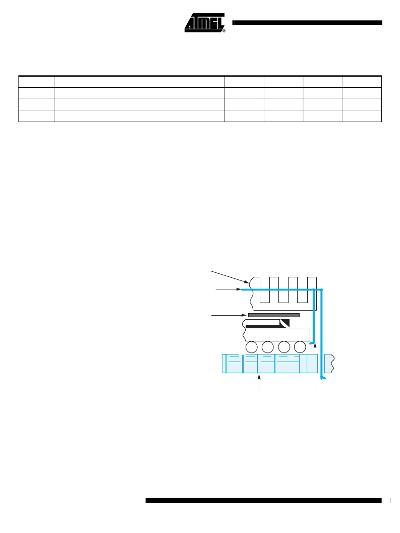
Figure7.
PackageExplodedCross-SectionalViewwithSeveralHeatSinkOptions
Ultimately,thefinalselectionofanappropriateheatsinkdependsonmanyfactors,such
asthermalperformanceatagivenairvelocity,spatialvolume,mass,attachment
method,assembly,andcost.
Table6.
ThermalSensorSpecifications
V
DD
=AV
DD
=L2AV
DD
=2.6V
DC
±
100mV,OV
DD
=L2OV
DD
=3.3±5%V
DC
,GND=0V
DC
,0
≤
T
j
<+125
°
C
Num
Characteristic
Min
Max
Unit
Notes
1
TemperatureRange
0
127
°
C
1
2
ComparatorSettlingTime
20
-
μs
2
3
Resolution
4
-
°
C
3
Adhesive
or
Thermal Interface Material
Heat Sink
CBGA Package
Heat Sink
Clip
Printed ± Circuit Board
Option
相關(guān)PDF資料 |
PDF描述 |
|---|---|
| TSPC750AVGSU12LH | Microprocessor |
| TSPC750AVGSU8LE | Microprocessor |
| TSPC750AVGSU8LH | Microprocessor |
| TSXPC750AMG12LH | Microprocessor |
| TSXPC750AMG8LE | Microprocessor |
相關(guān)代理商/技術(shù)參數(shù) |
參數(shù)描述 |
|---|---|
| TSPC750AVGSU12LH | 制造商:未知廠家 制造商全稱:未知廠家 功能描述:Microprocessor |
| TSPC750AVGSU8LE | 制造商:未知廠家 制造商全稱:未知廠家 功能描述:Microprocessor |
| TSPC750AVGSU8LH | 制造商:未知廠家 制造商全稱:未知廠家 功能描述:Microprocessor |
| TSPC750AVGU/T10LE | 制造商:未知廠家 制造商全稱:未知廠家 功能描述:Microprocessor |
| TSPC750AVGU/T10LH | 制造商:未知廠家 制造商全稱:未知廠家 功能描述:Microprocessor |
發(fā)布緊急采購,3分鐘左右您將得到回復(fù)。