- 您現(xiàn)在的位置:買賣IC網(wǎng) > PDF目錄98307 > TWL1101PFBR (TEXAS INSTRUMENTS INC) SPECIALTY CONSUMER CIRCUIT, PQFP48 PDF資料下載
參數(shù)資料
| 型號: | TWL1101PFBR |
| 廠商: | TEXAS INSTRUMENTS INC |
| 元件分類: | 消費家電 |
| 英文描述: | SPECIALTY CONSUMER CIRCUIT, PQFP48 |
| 封裝: | PLASTIC, TQFP-48 |
| 文件頁數(shù): | 29/31頁 |
| 文件大小: | 408K |
| 代理商: | TWL1101PFBR |
第1頁第2頁第3頁第4頁第5頁第6頁第7頁第8頁第9頁第10頁第11頁第12頁第13頁第14頁第15頁第16頁第17頁第18頁第19頁第20頁第21頁第22頁第23頁第24頁第25頁第26頁第27頁第28頁當(dāng)前第29頁第30頁第31頁

TWL1101
VOICE-BAND AUDIO PROCESSOR (VBAP
)
SLWS074A – MAY 1998 REVISED MARCH 1999
7
POST OFFICE BOX 655303
DALLAS, TEXAS 75265
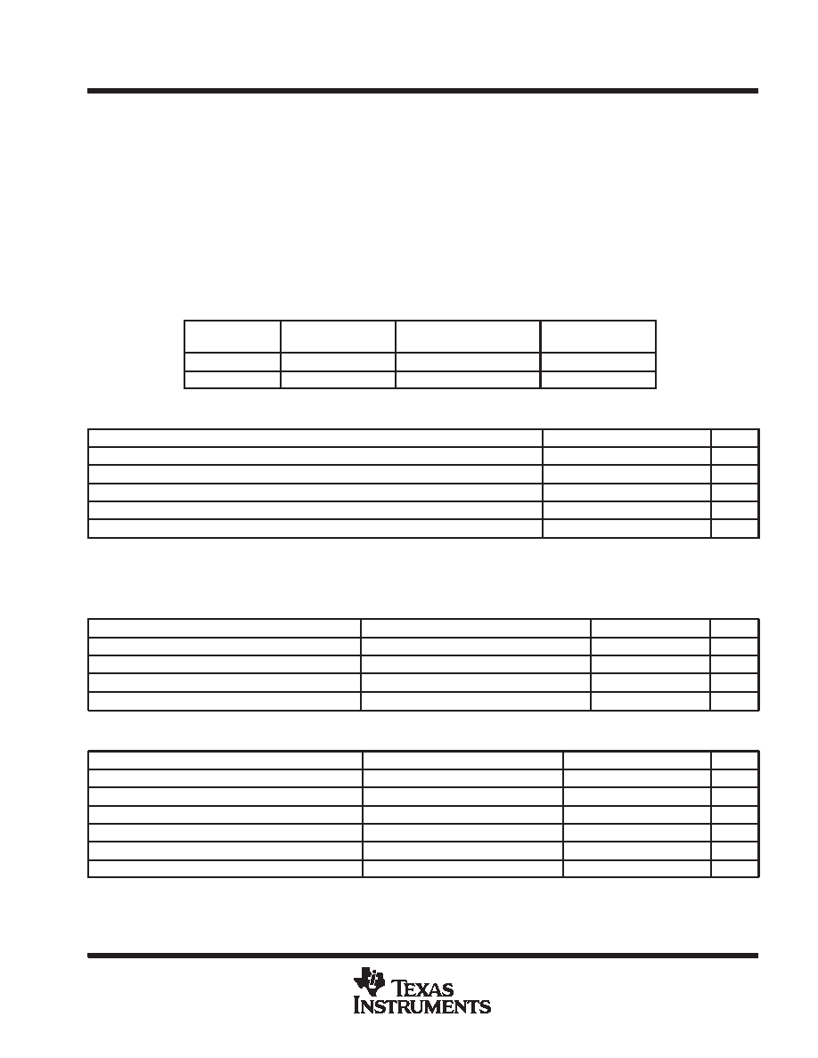
absolute maximum ratings over operating free-air temperature range (unless otherwise noted)
Supply voltage range
–0.3 V to 7.5 V
. . . . . . . . . . . . . . . . . . . . . . . . . . . . . . . . . . . . . . . . . . . . . . . . . . . . . . . . . . . . . .
Output voltage range at DOUT,VO
–0.3 V to 7.5 V
. . . . . . . . . . . . . . . . . . . . . . . . . . . . . . . . . . . . . . . . . . . . . . . . . . .
Input voltage range at DIN, VI
–0.3 V to 7.5 V
. . . . . . . . . . . . . . . . . . . . . . . . . . . . . . . . . . . . . . . . . . . . . . . . . . . . . . .
Continuous total power dissipation
See Dissipation Rating Table
. . . . . . . . . . . . . . . . . . . . . . . . . . . . . . . . . . . . . .
Operating free air temperature range (industrial temp)
–40
°C to 85°C
. . . . . . . . . . . . . . . . . . . . . . . . . . . . . . . . . .
Storage temperature range, testing
–65
°C to 150°C
. . . . . . . . . . . . . . . . . . . . . . . . . . . . . . . . . . . . . . . . . . . . . . . . .
Lead temperature 1,6 mm from case for 10 seconds
260
°C
. . . . . . . . . . . . . . . . . . . . . . . . . . . . . . . . . . . . . . . . . .
Stresses beyond those listed under “absolute maximum ratings” may cause permanent damage to the device. These are stress ratings only, and
functional operation of the device at these or any other conditions beyond those indicated under “recommended operating conditions” is not
implied. Exposure to absolute-maximum-rated conditions for extended periods may affect device reliability.
DISSIPATION RATING TABLE
PACKAGE
TA ≤25°C
POWER RATING
DERATING FACTOR
ABOVE TA = 25°C
TA = 85°C
POWER RATING
GGV
809 mW
9 mW/
°C
270 mW
PFB
916 mW
6.1 mW/
°C
552 mW
recommended operating conditions (see Notes 1 and 2)
MIN
NOM
MAX
UNIT
Supply voltage, AVDD, DVDD, PLLVDD, EARVDD
2.7
3.5
V
High-level input voltage (VIH)
0.7 x VDD
V
Low-level input voltage (VIL)
0.3 x VDD
V
Load impedance between EAR1OP and EAR1ON-RL (similar for EAR20)
32
Operating free-air temperature, TA (Industrial temp)
–40
85
_C
NOTES:
1. To avoid possible damage and resulting reliability problems to these CMOS devices, the power-up sequence detailed in the system
reliability features paragraph should be followed.
2. Voltages at analog inputs, outputs and VDD are with respect to VSS.
electrical characteristics over recommended ranges of supply voltage and free-air temperature
PARAMETER
TEST CONDITIONS
MIN
TYP
MAX
UNIT
I(dd)
Supply current from VDD
Operating, EAR1 selected
11
mA
I(dd)
Supply current from VDD
Operating, EAR2 selected
9
mA
I(dd)
Supply current from VDD
Power down
30
A
t(pu)
Power-up time from power down
60
ms
digital interface
PARAMETER
TEST CONDITIONS
MIN
TYP
MAX
UNIT
VOH
High-level output voltage PCMO
IOH = –3.2 mA VDD = 3 V
DVDD –0.2
V
VOL
Low-level output voltage PCMO
IOL = 3.2 mA VDD = 3 V
0.2
V
IIH
High-level input current, any digital input
VI = 2.2V to VDD
10
A
IIL
Low-level input current, any digital input
VI = 0 to .8 V
10
A
C(i)
Input capacitance
10
pF
C(o)
Output capacitance
20
pF
相關(guān)PDF資料 |
PDF描述 |
|---|---|
| TWL1102PBS | SPECIALTY CONSUMER CIRCUIT, PQFP32 |
| TWL1102PBSR | SPECIALTY CONSUMER CIRCUIT, PQFP32 |
| TWL1103PBS | SPECIALTY CONSUMER CIRCUIT, PQFP32 |
| TWL1103PBSR | SPECIALTY CONSUMER CIRCUIT, PQFP32 |
| TWL1103GQER | SPECIALTY CONSUMER CIRCUIT, PBGA80 |
相關(guān)代理商/技術(shù)參數(shù) |
參數(shù)描述 |
|---|---|
| TWL1102PBS | 功能描述:IC VOICE BAND AUDIO PROC 32-TQFP RoHS:是 類別:集成電路 (IC) >> 線性 - 音頻處理 系列:VBAP™ 其它有關(guān)文件:STA321 View All Specifications 標(biāo)準(zhǔn)包裝:1 系列:Sound Terminal™ 類型:音頻處理器 應(yīng)用:數(shù)字音頻 安裝類型:表面貼裝 封裝/外殼:64-LQFP 裸露焊盤 供應(yīng)商設(shè)備封裝:64-LQFP EP(10x10) 包裝:Digi-Reel® 其它名稱:497-11050-6 |
| TWL1103 | 制造商:TI 制造商全稱:Texas Instruments 功能描述:VOICE-BAND AUDIO PROCESSOR VBAPE |
| TWL1103GQE | 制造商:Rochester Electronics LLC 功能描述:- Bulk 制造商:Texas Instruments 功能描述: |
| TWL1103GQER | 功能描述:VOICE BAND AUDIO PROC 80-BGA RoHS:否 類別:集成電路 (IC) >> 線性 - 音頻處理 系列:VBAP™ 其它有關(guān)文件:STA321 View All Specifications 標(biāo)準(zhǔn)包裝:1 系列:Sound Terminal™ 類型:音頻處理器 應(yīng)用:數(shù)字音頻 安裝類型:表面貼裝 封裝/外殼:64-LQFP 裸露焊盤 供應(yīng)商設(shè)備封裝:64-LQFP EP(10x10) 包裝:Digi-Reel® 其它名稱:497-11050-6 |
| TWL1103PBS | 制造商:Rochester Electronics LLC 功能描述:- Bulk |
發(fā)布緊急采購,3分鐘左右您將得到回復(fù)。