- 您現(xiàn)在的位置:買賣IC網(wǎng) > PDF目錄98307 > TWL1102PBS (TEXAS INSTRUMENTS INC) SPECIALTY CONSUMER CIRCUIT, PQFP32 PDF資料下載
參數(shù)資料
| 型號(hào): | TWL1102PBS |
| 廠商: | TEXAS INSTRUMENTS INC |
| 元件分類: | 消費(fèi)家電 |
| 英文描述: | SPECIALTY CONSUMER CIRCUIT, PQFP32 |
| 封裝: | PLASTIC, TQFP-32 |
| 文件頁(yè)數(shù): | 28/29頁(yè) |
| 文件大?。?/td> | 387K |
| 代理商: | TWL1102PBS |
第1頁(yè)第2頁(yè)第3頁(yè)第4頁(yè)第5頁(yè)第6頁(yè)第7頁(yè)第8頁(yè)第9頁(yè)第10頁(yè)第11頁(yè)第12頁(yè)第13頁(yè)第14頁(yè)第15頁(yè)第16頁(yè)第17頁(yè)第18頁(yè)第19頁(yè)第20頁(yè)第21頁(yè)第22頁(yè)第23頁(yè)第24頁(yè)第25頁(yè)第26頁(yè)第27頁(yè)當(dāng)前第28頁(yè)第29頁(yè)

TWL1102
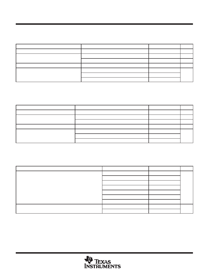
VOICE-BAND AUDIO PROCESSOR (VBAP
)
SLVS264 – NOVEMBER 1999
8
POST OFFICE BOX 655303
DALLAS, TEXAS 75265
electrical characteristics at 2.7 V and 25
° C (unless otherwise noted) (continued)
transmit gain and dynamic range, companded mode (
-law or A-law) or linear mode selected, transmit slope
filter bypassed (see Notes 7 and 8)
PARAMETER
TEST CONDITIONS
MIN
TYP
MAX
UNIT
Transmit reference-signal level (0dB)
Differential
175
mVpp
Overload signal level (3 dBm0)
Differential, normal mode
248
mVpp
Overload-signal level (3 dBm0)
Differential, extended mode
63
mVpp
Absolute gain error
0 dBm0 input signal, VDD = 2.7 V (minimum)
–1
1
dB
Gi
ith i
t l
l
lti
t
i
t
MIC1N, MIC1P to PCMO at 3 dBm0 to –30 dBm0
– 0.5
0.5
Gain error with input level relative to gain at
–10 dBm0 MIC1N MIC1P to PCMO
MIC1N, MIC1P to PCMO at –31 dBm0 to –45 dBm0
–1
1
dB
–10 dBm0 MIC1N, MIC1P to PCMO
MIC1N, MIC1P to PCMO at –46 dBm0 to –55 dBm0
–1.2
1.2
dB
NOTES:
7. Unless otherwise noted, the analog input is 0 dB, 1020-Hz sine wave, where 0 dB is defined as the zero-reference point of the channel
under test.
8. The reference signal level, which is input to the transmit channel, is defined as a value 3 dB below the full-scale value of 88-mVrms.
transmit gain and dynamic range, companded mode (
-law or A-law) or linear mode selected, transmit slope
filter enabled (see Notes 9 and 10)
PARAMETER
TEST CONDITIONS
MIN
TYP
MAX
UNIT
Transmit reference-signal level (0dB)
Differential
175
mVpp
Overload signal level (3 dBm0)
Differential, normal mode
248
mVpp
Overload-signal level (3 dBm0)
Differential, extended mode
63
mVpp
Absolute gain error
0 dBm0 input signal, VDD = 2.7 V (minimum)
–1
1
dB
Gi
ith i
t l
l
lti
t
i
t
MIC1N, MIC1P to PCMO at 3 dBm0 to –30 dBm0
–0.5
0.5
Gain error with input level relative to gain at
–10 dBm0 MIC1N MIC1P to PCMO
MIC1N, MIC1P to PCMO at –31 dBm0 to –45 dBm0
–1
1
dB
–10 dBm0 MIC1N, MIC1P to PCMO
MIC1N, MIC1P to PCMO at –46 dBm0 to –55 dBm0
–1.2
1.2
dB
NOTES:
9. Unless otherwise noted, the analog input is 0 dB, 1020-Hz sine wave, where 0 dB is defined as the zero-reference point of the channel
under test.
10. The reference signal level, which is input to the transmit channel, is defined as a value 3 dB below the full-scale value of 88-mVrms.
transmit filter transfer, companded mode (
-law or A-law) or linear mode selected, transmit slope filter
bypassed, external high pass filter bypassed (MCLK = 2.048 MHz)
PARAMETER
TEST CONDITIONS
MIN
TYP
MAX
UNIT
fMIC1 or fMIC2 <100 Hz
–0.5
0.5
fMIC1 or fMIC2 = 200 Hz
–0.5
0.5
G i
l ti
t i
l
i
t 1020 H
i t
l hi h
fMIC1 or fMIC2 = 300 Hz to 3 kHz
–0.5
0.5
Gain relative to input signal gain at 1020 Hz, internal high-pass
filter disabled
fMIC1 or fMIC2 = 3.4 kHz
–1.5
0
dB
filter disabled.
fMIC1 or fMIC2 = 4 kHz
–14
dB
fMIC1 or fMIC2 = 4.6 kHz
–35
fMIC1 or fMIC2 = 8 k Hz
–47
Gain relative to input signal gain at 1020 Hz, internal high-pass
fMIC1 or fMIC2 <100 Hz
–15
dB
Gain relative to in ut signal gain at 1020 Hz, internal high ass
filter enabled.
fMIC1 or fMIC2 = 200 Hz
–5
dB
相關(guān)PDF資料 |
PDF描述 |
|---|---|
| TWL1102PBSR | SPECIALTY CONSUMER CIRCUIT, PQFP32 |
| TWL1103PBS | SPECIALTY CONSUMER CIRCUIT, PQFP32 |
| TWL1103PBSR | SPECIALTY CONSUMER CIRCUIT, PQFP32 |
| TWL1103GQER | SPECIALTY CONSUMER CIRCUIT, PBGA80 |
| TWL1103TPBSQ1 | SPECIALTY CONSUMER CIRCUIT, PQFP32 |
相關(guān)代理商/技術(shù)參數(shù) |
參數(shù)描述 |
|---|---|
| TWL1103 | 制造商:TI 制造商全稱:Texas Instruments 功能描述:VOICE-BAND AUDIO PROCESSOR VBAPE |
| TWL1103GQE | 制造商:Rochester Electronics LLC 功能描述:- Bulk 制造商:Texas Instruments 功能描述: |
| TWL1103GQER | 功能描述:VOICE BAND AUDIO PROC 80-BGA RoHS:否 類別:集成電路 (IC) >> 線性 - 音頻處理 系列:VBAP™ 其它有關(guān)文件:STA321 View All Specifications 標(biāo)準(zhǔn)包裝:1 系列:Sound Terminal™ 類型:音頻處理器 應(yīng)用:數(shù)字音頻 安裝類型:表面貼裝 封裝/外殼:64-LQFP 裸露焊盤(pán) 供應(yīng)商設(shè)備封裝:64-LQFP EP(10x10) 包裝:Digi-Reel® 其它名稱:497-11050-6 |
| TWL1103PBS | 制造商:Rochester Electronics LLC 功能描述:- Bulk |
| TWL1103PBSR | 制造商:Rochester Electronics LLC 功能描述:- Bulk |
發(fā)布緊急采購(gòu),3分鐘左右您將得到回復(fù)。