- 您現(xiàn)在的位置:買賣IC網(wǎng) > PDF目錄378720 > uA723D (Texas Instruments, Inc.) PRECISION VOLTAGE REGULATORS PDF資料下載
參數(shù)資料
| 型號: | uA723D |
| 廠商: | Texas Instruments, Inc. |
| 英文描述: | PRECISION VOLTAGE REGULATORS |
| 中文描述: | 精密電壓調(diào)節(jié)器 |
| 文件頁數(shù): | 3/17頁 |
| 文件大?。?/td> | 469K |
| 代理商: | UA723D |
μ
A723
PRECISION VOLTAGE REGULATORS
SLVS057D – AUGUST 1972 – REVISED JULY 1999
3
POST OFFICE BOX 655303
DALLAS, TEXAS 75265
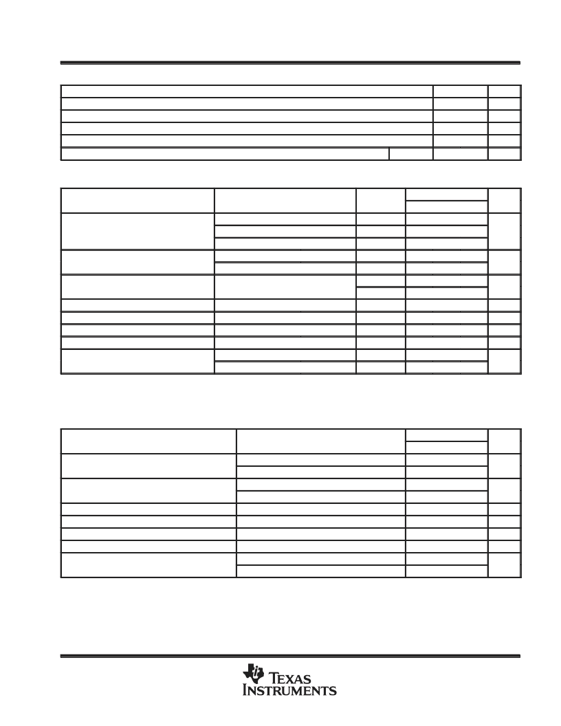
recommended operating conditions
MIN
MAX
UNIT
Input voltage, VI
Output voltage, VO
Input-to-output voltage differential, VC – VO
Output current, IO
Operating free-air temperature range, TA
9.5
40
V
2
37
V
3
38
V
150
mA
°
C
μ
A723C
0
70
electrical characteristics at specified free-air temperature (see Notes 3 and 4)
PARAMETER
TEST CONDITIONS
TA
μ
A723C
TYP
UNIT
MIN
MAX
VI = 12 V to VI = 15 V
VI = 12 V to VI = 40 V
VI = 12 V to VI = 15 V
f = 50 Hz to 10 kHz,
25
°
C
25
°
C
0.1
1
Input regulation
1
5
mV/V
0
°
C to 70
°
C
25
°
C
25
°
C
25
°
C
0
°
C to 70
°
C
25
°
C
25
°
C
0
°
C to 70
°
C
25
°
C
25
°
C
25
°
C
3
Ripple rejection
Cref = 0
Cref = 5
μ
F
74
dB
f = 50 Hz to 10 kHz,
86
Output regulation
–0.3
–2
mV/V
–6
Reference voltage, Vref
Standby current
6.8
7.15
7.5
V
VI = 30 V,
IO = 0
2.3
4
mA
%/
°
C
mA
Temperature coefficient of output voltage
0.003
0.015
Short-circuit output current
RSC = 10
,
BW = 100 Hz to 10 kHz,
BW = 100 Hz to 10 kHz,
VO = 0
Cref = 0
Cref = 5
μ
F
65
Output noise voltage
20
2.5
μ
V
NOTES:
3. For all values in this table, the device is connected as shown in Figure 1 with the divider resistance as seen by the error amplifier
≤
10 k
. Unless otherwise specified, VI = VCC+ = VC = 12 V, VCC– = 0, VO = 5 V, IO = 1 mA, RSC = 0, and Cref = 0.
4. Pulse-testing techniques must be used that will maintain the junction temperature as close to the ambient temperature as possible.
electrical characteristics, T
A
= 25
°
C (see Notes 3 and 4)
PARAMETER
TEST CONDITIONS
μ
A723Y
TYP
UNIT
MIN
MAX
Input regulation
VI = 12 V to VI = 15 V
VI = 12 V to VI = 40 V
f = 50 Hz to 10 kHz,
0.1
mV/V
1
Ripple rejection
Cref = 0
Cref = 5
μ
F
74
dB
f = 50 Hz to 10 kHz,
86
Output regulation
–0.3
mV/V
Reference voltage, Vref
Standby current
7.15
V
VI = 30 V,
RSC = 10
,
BW = 100 Hz to 10 kHz,
BW = 100 Hz to 10 kHz,
IO = 0
VO = 0
Cref = 0
Cref = 5
μ
F
2.3
mA
Short-circuit output current
65
mA
Output noise voltage
20
2.5
μ
V
NOTES:
3. For all values in this table, the device is connected as shown in Figure 1 with the divider resistance as seen by the error amplifier
≤
10 k
. Unless otherwise specified, VI = VCC+ = VC = 12 V, VCC– = 0, VO = 5 V, IO = 1 mA, RSC = 0, and Cref = 0.
4. Pulse-testing techniques must be used that will maintain the junction temperature as close to the ambient temperature as possible.
相關(guān)PDF資料 |
PDF描述 |
|---|---|
| uA723N | PRECISION VOLTAGE REGULATORS |
| UA747C | DUAL GENERAL-PURPOSE OPERATIONAL AMPLIFIERS |
| SA747CN | Voltage-Feedback Operational Amplifier |
| UA747-1MJB | Octal channel high side driver |
| UA747CN-B | Voltage-Feedback Operational Amplifier |
相關(guān)代理商/技術(shù)參數(shù) |
參數(shù)描述 |
|---|---|
| UA723DC | 制造商:FCS 功能描述: |
| UA723F | 制造商:PHILIPS 制造商全稱:NXP Semiconductors 功能描述:Precision voltage regulator |
| UA723F-B | 制造商:未知廠家 制造商全稱:未知廠家 功能描述:Positive Adjustable Voltage Regulator |
| UA723HC | 制造商:Freescale Semiconductor 功能描述: 制造商: 功能描述: 制造商:undefined 功能描述: |
| UA723HMQB | 制造商:UNKNOWN 功能描述: |
發(fā)布緊急采購,3分鐘左右您將得到回復。