- 您現(xiàn)在的位置:買賣IC網(wǎng) > PDF目錄379479 > UCC1801L (Texas Instruments, Inc.) Low-Power BiCMOS Current-Mode PWM PDF資料下載
參數(shù)資料
| 型號: | UCC1801L |
| 廠商: | Texas Instruments, Inc. |
| 英文描述: | Low-Power BiCMOS Current-Mode PWM |
| 中文描述: | 低功耗BiCMOS電流模式PWM |
| 文件頁數(shù): | 2/20頁 |
| 文件大小: | 383K |
| 代理商: | UCC1801L |
2
UCC1800/1/2/3/4/5
UCC2800/1/2/3/4/5
UCC3800/1/2/3/4/5
DIL-8, SOIC-8 (Top View)
J or N, D Package
OUT
VCC
REF
GND
1
2
3
4
8
7
6
5
FB
COMP
CS
RC
ABSOLUTE MAXIMUM RATINGS (Note 1)
V
CC
Voltage (Note 2). . . . . . . . . . . . . . . . . . . . . . . . . . . . 12.0V
V
CC
Current (Note 2) . . . . . . . . . . . . . . . . . . . . . . . . . . 30.0mA
OUT Current. . . . . . . . . . . . . . . . . . . . . . . . . . . . . . . . . . .
±
1.0A
OUT Energy (Capacitive Load) . . . . . . . . . . . . . . . . . . . 20.0
μ
J
Analog Inputs (FB, CS) . . . . . . . . . . . . . . . . . . . . –0.3V to 6.3V
Power Dissipation at T
A
< +25°C (N or J Package) . . . . . 1.0W
Power Dissipation at T
A
< +25°C (D Package). . . . . . . . 0.65W
Power Dissipation at T
A
< +25°C (L Package) . . . . . . . 1.375W
Storage Temperature Range. . . . . . . . . . . . .
–
65°C to +150°C
Lead Temperature (Soldering, 10 Seconds) . . . . . . . . +300°C
Note 1: Values beyond which damage may occur. All voltages
are with respect to GND. All currents are positive into
the specified terminal. Consult Unitrode databook for
information regarding thermal specifications and limita-
tions of packages.
Note 2: In normal operation V
CC
is powered through a current
limiting resistor. Absolute maximum of 12V applies
when V
CC
is driven from a low impedance source such
that I
CC
does not exceed 30mA (which includes gate
drive current requirement). The resistor should be
sized so that the V
CC
voltage, under operating condi-
tions is below 12V but above the turn off threshold.
COMP
FB
CS
RC
REF
VCC
OUT
GND
8
7
6
5
1
2
3
4
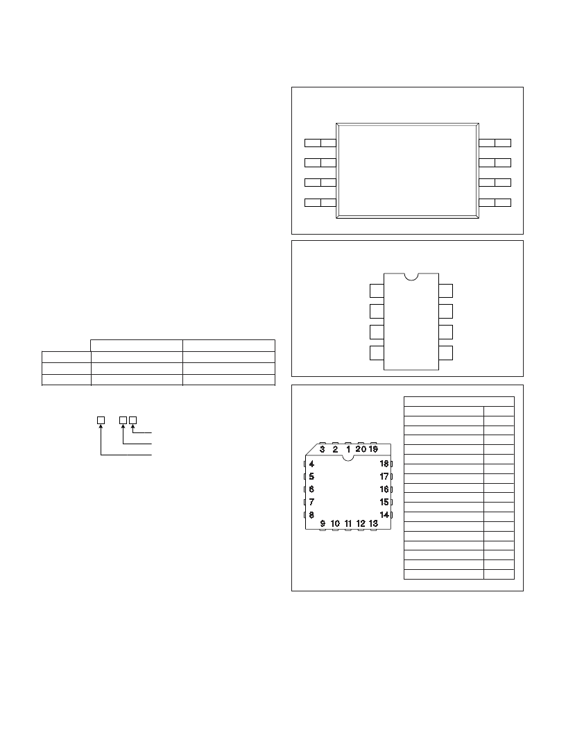
CONNECTION DIAGRAMS
TSSOP-8 (Top View)
PW Package
UCC
PRODUCT OPTION
PACKAGE
80
TEMPERATURE RANGE
ORDERING INFORMATION
Temperature Range
–55°C to +125°C
–40°C to +85°C
0°C to +70°C
Available Packages
J, L
N, D, PW
N, D, PW
UCC180X
UCC280X
UCC380X
TEMPERATURE AND PACKAGE SELECTION
LCC-20
(TOP VIEW)
L Package
PACKAGE PIN FUNCTION
FUNCTION
N/C
Comp
N/C
FB
N/C
CS
N/C
RC
N/C
PWR GND
GND
N/C
OUT
N/C
VCC
N/C
REF
PIN
1
2
3-4
5
6
7
8-9
10
11
12
13
14
15
16
17
18-19
20
相關(guān)PDF資料 |
PDF描述 |
|---|---|
| UCC1802L | Low-Power BiCMOS Current-Mode PWM |
| UCC3800PWTR | Low-Power BiCMOS Current-Mode PWM |
| UCC3800PWTRG4 | CMOS |
| UCC1804L | Low-Power BiCMOS Current-Mode PWM |
| UCC2801PWTR | Low-Power BiCMOS Current-Mode PWM |
相關(guān)代理商/技術(shù)參數(shù) |
參數(shù)描述 |
|---|---|
| UCC1801L883B | 制造商:Texas Instruments 功能描述:BICMOS PWM - Rail/Tube |
| UCC1802 | 制造商:TI 制造商全稱:Texas Instruments 功能描述:Low-Power BiCMOS Current-Mode PWM |
| UCC1802J | 制造商:Texas Instruments 功能描述:Current Mode PWM Controller 1A 8-Pin CDIP Tube 制造商:Texas Instruments 功能描述:CURRENT MODE PWM CNTRLR 1A 8CDIP - Rail/Tube |
| UCC1802J883B | 制造商:Texas Instruments 功能描述:Current Mode PWM Controller 1A 8-Pin CDIP Tube |
| UCC1802L | 制造商:Texas Instruments 功能描述:CURRENT MODE PWM CNTRLR 1A 20LCCC - Rail/Tube |
發(fā)布緊急采購,3分鐘左右您將得到回復。