- 您現(xiàn)在的位置:買賣IC網(wǎng) > PDF目錄225404 > UEP0J331MED.PD (Nichicon Corporation) USB Positive Overvoltage Protection Controller PDF資料下載
參數(shù)資料
| 型號(hào): | UEP0J331MED.PD |
| 廠商: | Nichicon Corporation |
| 英文描述: | USB Positive Overvoltage Protection Controller |
| 中文描述: | 鋁電解電容器 |
| 文件頁數(shù): | 1/1頁 |
| 文件大?。?/td> | 77K |
| 代理商: | UEP0J331MED.PD |
U
1
E
2
P
3
1
4
A
5
4
6
7
0
8
M
9
D
10
D
11
Configuration
Capacitance tolerance (±20%)
Rated Capacitance (47mF)
Rated voltage (10V)
Series name
Type
fD
P
fd
5
2.0
0.5
6.3
2.5
0.5
8
3.5
0.6
10
5.0
0.6
12.5
5.0
0.6
16
7.5
0.8
18
7.5
0.8
(L < 20) 1.5
(L 20) 2.0
f D
5
Pb-free leadwire
Pb-free PET sleeve
DD
6.3
ED
8á 10
PD
12.5 ~ 18
HD
Configuration
(mm)
(f6.3up)
15MIN
4MIN
Sleeve (P.E.T.)
Pressure
relief vent
fd
fD
+
0.5
MAX
L+ MAX
P
±
0.5
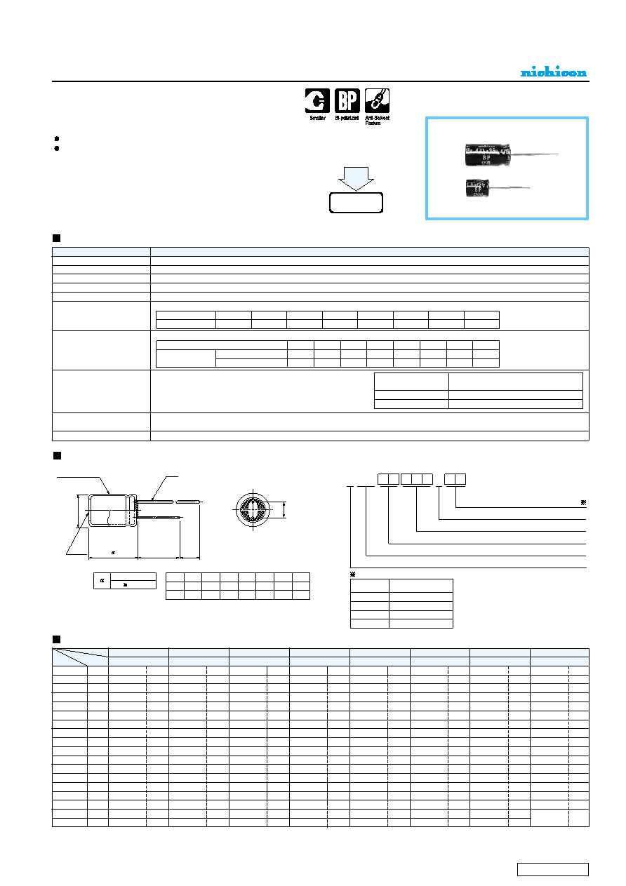
ALUMINUM ELECTROLYTIC CAPACITORS
EP
series
Bi-Polarized, Wide Temperature Range
1 ~ 2 ranks smaller than ET series.
Adapted to the RoHS directive (2002/95/EC).
Radial Lead Type
Type numbering system (Example : 10V 47F)
Specifications
Category Temperature Range
Rated Voltage Range
Rated Capacitance Range
Capacitance Tolerance
Leakage Current
tan
δ
Stability at Low Temperature
Endurance
Shelf Life
Marking
Performance Characteristics
Item
– 55 ~ +105°C
6.3 ~ 100V
0.47 ~ 6800F
± 20% at 120Hz, 20°C
After 5 minutes' application of rated voltage, leakage current is not more than 0.03CV or 3 (A), whichever is greater.
Printed with white color letter on black sleeve.
Measurement frequency : 120Hz, Temperature : 20°C
Measurement frequency : 120Hz
After 1000 hours' application of rated voltage at 105°C, with the
polarity inverted every 250 hours, capacitors meet the
characteristic requirements listed at right.
After storing the capacitors under no load at 105°C for 1000 hours, and after performing voltage treatment based on JIS C 5101-4
clause 4.1 at 20°C, they will meet the specified value for endurance characteristics listed above.
EP
ET
Rated voltage (V)
tan
δ (MAX.)
6.3
0.24
10
0.24
16
0.20
25
0.20
35
0.16
50
0.14
63
0.12
100
0.10
Z– 25°C / Z+20°C
Z– 40°C / Z+20°C
Rated voltage (V)
Impedance ratio
ZT / Z20 (MAX.)
6.3
4
10
3
8
16
2
6
25
2
4
35
2
3
50
2
3
63
2
3
100
2
3
Smaller
Leakage current
tan
δ
Capacitance change
Within ±25% of initial value (6.3~16V)
Within ±20% of initial value (25~100V)
150% or less of initial specified value
Initial specified value or less
Please refer to page 21, 22, 23 about the formed or taped product spec.
Please refer to page 3 for the minimum order quantity.
5
× 11
5
× 11
6.3
× 11
6.3
× 11
6.3
× 11
8
× 11.5
10
× 16
12.5
× 20
12.5
× 20
16
× 25
18
× 35.5
37
45
54
90
150
240
290
510
910
1200
1520
5
× 11
5
× 11
5
× 11
5
× 11
5
× 11
6.3
× 11
8
× 11.5
8
× 11.5
10
× 12.5
10
× 20
12.5
× 25
16
× 25
16
× 31.5
8
12
20
25
30
50
97
140
170
300
510
Rated
ripple
20
24
40
68
98
130
225
405
535
680
7
10
15
18
22
37
63
77
105
190
340
460
590
21
30
51
72
86
160
290
350
465
805
27
40
49
67
110
195
265
345
605
1070
1400
5
× 11
5
× 11
5
× 11
6.3
× 11
8
× 11.5
10
× 16
10
× 16
12.5
× 20
16
× 25
16
× 31.5
18
× 35.5
0.47
1
2.2
3.3
4.7
10
22
33
47
100
220
330
470
1000
2200
3300
4700
6800
Dimensions
R47
010
2R2
3R3
4R7
100
220
330
470
101
221
331
471
102
222
332
472
682
5
× 11
5
× 11
6.3
× 11
8
× 11.5
8
× 11.5
10
× 12.5
10
× 20
12.5
× 25
16
× 25
16
× 31.5
18
× 35.5
45
54
90
150
185
260
460
820
1110
1430
1830
0J
Rated Ripple (mArms) at 105°C 120Hz
6.3
1A
10
1C
16
1E
25
1V
35
1H
50
1J
2A
63
100
5
× 11
5
× 11
5
× 11
6.3
× 11
8
× 11.5
10
× 12.5
10
× 16
10
× 20
12.5
× 25
16
× 31.5
18
× 35.5
5
× 11
5
× 11
6.3
× 11
8
× 11.5
8
× 11.5
10
× 16
12.5
× 20
12.5
× 20
12.5
× 25
16
× 31.5
5
× 11
6.3
× 11
6.3
× 11
8
× 11.5
10
× 12.5
10
× 16
12.5
× 20
16
× 25
16
× 31.5
18
× 35.5
5
× 11
6.3
× 11
6.3
× 11
6.3
× 11
8
× 11.5
10
× 16
12.5
× 20
12.5
× 20
16
× 25
18
× 35.5
27
46
56
67
110
215
320
380
670
1140
Case size
φD×L (mm)
V
Code
Cap. (F)
Please refer to page 21 about the end seal configulation.
CAT.8100V
相關(guān)PDF資料 |
PDF描述 |
|---|---|
| UER | FEMALE, STRAIGHT TWO PART BOARD CONNECTOR, SOLDER |
| UFD14P50/501L7 | FIBER OPTIC SPLITTER/COUPLER, 1X4PORT, 50/50, LC/UPC CONNECTOR |
| UFD66A50/501R3 | FIBER OPTIC SPLITTER/COUPLER, 6X6PORT, 50/50, SC/PC CONNECTOR |
| UFD66A50/501R2 | FIBER OPTIC SPLITTER/COUPLER, 6X6PORT, 50/50, FC/APC CONNECTOR |
| UFD66A50/501R1 | FIBER OPTIC SPLITTER/COUPLER, 6X6PORT, 50/50, FC/PC CONNECTOR |
相關(guān)代理商/技術(shù)參數(shù) |
參數(shù)描述 |
|---|---|
| UEP0J331MHD | 制造商:NICHICON 制造商全稱:Nichicon corporation 功能描述:ALUMINUM ELECTROLYTIC CAPACITORS |
| UEP0J331MPD | 功能描述:鋁質(zhì)電解電容器 - 帶引線 6.3volts 330uF 0.2L/S RoHS:否 制造商:Kemet 引線類型: 電容:220 uF 容差:20 % 電壓額定值:25 V 工作溫度范圍: 端接類型:Radial 外殼直徑:8 mm 外殼長度:11 mm 引線間隔:5 mm 產(chǎn)品:General Purpose Electrolytic Capacitors 封裝:Bulk |
| UEP0J332MDD | 制造商:NICHICON 制造商全稱:Nichicon corporation 功能描述:ALUMINUM ELECTROLYTIC CAPACITORS |
| UEP0J332MED.PD | 制造商:NICHICON 制造商全稱:Nichicon corporation 功能描述:ALUMINUM ELECTROLYTIC CAPACITORS |
| UEP0J332MHD | 功能描述:鋁質(zhì)電解電容器 - 帶引線 6.3volts 3300uF 0.2L/S RoHS:否 制造商:Kemet 引線類型: 電容:220 uF 容差:20 % 電壓額定值:25 V 工作溫度范圍: 端接類型:Radial 外殼直徑:8 mm 外殼長度:11 mm 引線間隔:5 mm 產(chǎn)品:General Purpose Electrolytic Capacitors 封裝:Bulk |
發(fā)布緊急采購,3分鐘左右您將得到回復(fù)。