- 您現(xiàn)在的位置:買賣IC網(wǎng) > PDF目錄378741 > UPD65808 ASIC PDF資料下載
參數(shù)資料
| 型號(hào): | UPD65808 |
| 英文描述: | ASIC |
| 中文描述: | 專用集成電路 |
| 文件頁數(shù): | 36/64頁 |
| 文件大?。?/td> | 399K |
| 代理商: | UPD65808 |
第1頁第2頁第3頁第4頁第5頁第6頁第7頁第8頁第9頁第10頁第11頁第12頁第13頁第14頁第15頁第16頁第17頁第18頁第19頁第20頁第21頁第22頁第23頁第24頁第25頁第26頁第27頁第28頁第29頁第30頁第31頁第32頁第33頁第34頁第35頁當(dāng)前第36頁第37頁第38頁第39頁第40頁第41頁第42頁第43頁第44頁第45頁第46頁第47頁第48頁第49頁第50頁第51頁第52頁第53頁第54頁第55頁第56頁第57頁第58頁第59頁第60頁第61頁第62頁第63頁第64頁
36
μ
PD64A, 65
Data Sheet U14380EJ2V0DS00
9.4 Accumulator Operation Instructions
ANL A, R0n
ANL A, R1n
<1> Instruction code
<2> Cycle count
<3> Function
:
1 1 0 1 R
4
0 R
3
R
2
R
1
R
0
: 1
: (A)
←
(A)
CY
←
A
3
Rmn
3
∨
(Rmn)
m = 0, 1
n = 0 to F
The accumulator contents and the register Rmn contents are ANDed and the results are entered in the
accumulator.
ANL A, @R0H
ANL A, @R0L
<1> Instruction code
<2> Cycle count
<3> Function
:
1 1 0 1 0/1 1 0 0 0 0
: 1
: (A)
←
(A)
CY
←
A
3
ROM
7
(A)
←
(A)
CY
←
A
3
ROM
3
∨
((P13), (R0))
7-4
(in the case of ANL A, @R0H)
∨
((P13), (R0))
3-0
(in the case of ANL A, @R0L)
The accumulator contents and the program memory contents specified with the control register P13 and
register pair R
10
-R
00
are ANDed and the results are entered in the accumulator.
If H is specified, b
7
, b
6
, b
5
and b
4
take effect. If L is specified, b
3
, b
2
, b
1
and b
0
take effect.
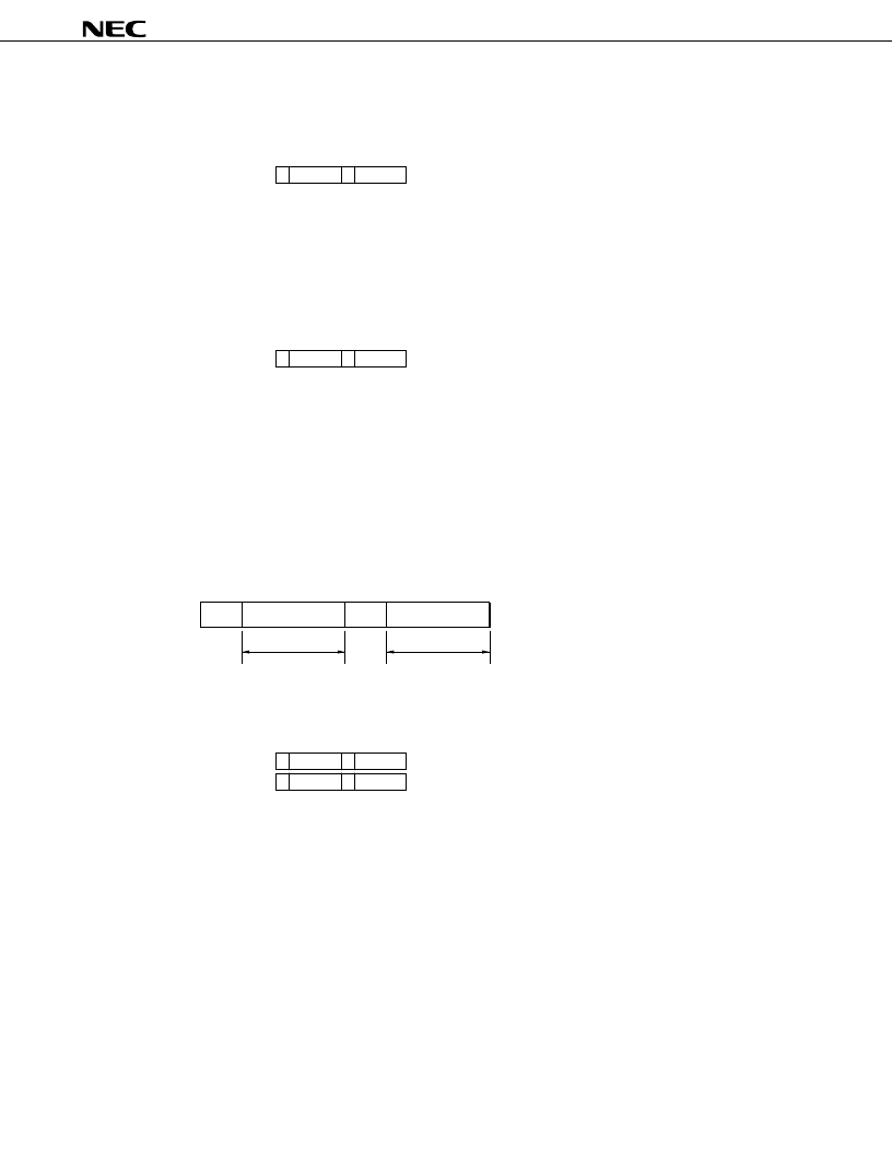
Program memory (ROM) organization
b
9
b
8
b
7
b
6
b
5
b
4
b
3
b
2
b
1
b
0
H
↓
L
↓
Valid bits at the time of accumulator operation
ANL A, #data4
<1> Instruction code
:
1 1 0 1 1 1 0 0 0 1
0 0 0 0 0 0 d
3
d
2
d
1
d
0
: 1
: (A)
←
(A)
CY
←
A
3
data4
3
<2> Cycle count
<3> Function
∨
data4
The accumulator contents and the immediate data are ANDed and the results are entered in the
accumulator.
相關(guān)PDF資料 |
PDF描述 |
|---|---|
| UPD65808-QFP100P.63SQ | ASIC |
| UPD65808-QFP100P.7X.9 | ASIC |
| UPD65808-QFP120P.63SQ | ASIC |
| UPD65808-QFP120P1.2SQ | ASIC |
| UPD65808-QFP160P1.2SQ | ASIC |
相關(guān)代理商/技術(shù)參數(shù) |
參數(shù)描述 |
|---|---|
| UPD65808-QFP100P.63SQ | 制造商:未知廠家 制造商全稱:未知廠家 功能描述:ASIC |
| UPD65808-QFP100P.7X.9 | 制造商:未知廠家 制造商全稱:未知廠家 功能描述:ASIC |
| UPD65808-QFP120P.63SQ | 制造商:未知廠家 制造商全稱:未知廠家 功能描述:ASIC |
| UPD65808-QFP120P1.2SQ | 制造商:未知廠家 制造商全稱:未知廠家 功能描述:ASIC |
| UPD65808-QFP160P1.2SQ | 制造商:未知廠家 制造商全稱:未知廠家 功能描述:ASIC |
發(fā)布緊急采購,3分鐘左右您將得到回復(fù)。