- 您現(xiàn)在的位置:買賣IC網(wǎng) > PDF目錄383983 > UPD75004CU (NEC Corp.) 4-BIT SINGLE-CHIP MICROCOMPUTER PDF資料下載
參數(shù)資料
| 型號: | UPD75004CU |
| 廠商: | NEC Corp. |
| 英文描述: | 4-BIT SINGLE-CHIP MICROCOMPUTER |
| 中文描述: | 4位單片機 |
| 文件頁數(shù): | 9/66頁 |
| 文件大小: | 542K |
| 代理商: | UPD75004CU |
第1頁第2頁第3頁第4頁第5頁第6頁第7頁第8頁當(dāng)前第9頁第10頁第11頁第12頁第13頁第14頁第15頁第16頁第17頁第18頁第19頁第20頁第21頁第22頁第23頁第24頁第25頁第26頁第27頁第28頁第29頁第30頁第31頁第32頁第33頁第34頁第35頁第36頁第37頁第38頁第39頁第40頁第41頁第42頁第43頁第44頁第45頁第46頁第47頁第48頁第49頁第50頁第51頁第52頁第53頁第54頁第55頁第56頁第57頁第58頁第59頁第60頁第61頁第62頁第63頁第64頁第65頁第66頁
μ
PD75004, 75006, 75008
9
3.
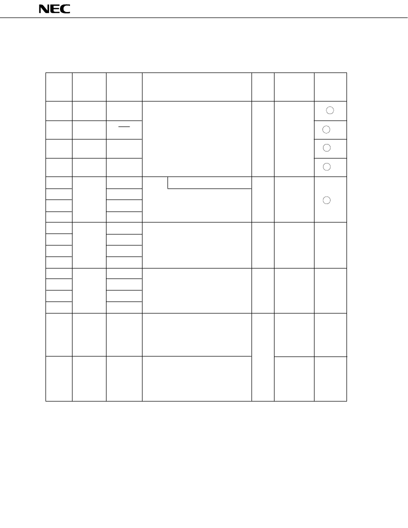
PIN FUNCTIONS
3.1
PORT PINS (1/2)
Input/
Output
Circuit
TYPE*
1
P00
P01
P02
P03
P10
P11
P12
P13
P20
P21
P22
P23
P30*
2
P31*
2
P32*
2
P33*
2
P40-43*
2
P50-53*
2
Pin Name
Input/Output
Function
8-Bit I/O
When Reset
Also Served
As
INT4
SCK
SO/SB0
SO/SB1
INT0
INT1
INT2
TI0
PTO0
—
PCL
BUZ
—
—
—
—
—
—
4-bit input port (PORT0)
Pull-up resistors can be specified in 3-bit
units for the P01 to P03 pins by software.
With noise elimination function
4-bit input port (PORT1)
Internal pull-up resistors can be
specified in 4-bit units by software.
4-bit input/output port (PORT2)
Internal pull-up resistors can be
specified in 4-bit units by software.
Programmable 4-bit input/output port
(PORT3)
This port can be specified for input/
output in bit units.
Internal pull-up resistors can be
specified in 4-bit units by software.
N-ch open-drain 4-bit input/output port
(PORT4)
Internal pull-up resistors can be
specified in bit units. (mask option)
Resistive voltage is 10 V in the open-
drain mode.
N-ch open-drain 4-bit input/output port
(PORT5)
Internal pull-up resistors can be
specified in bit units. (mask option)
Resistive voltage is 10 V in the open-
drain mode.
Input
Input
Input
Input
High level
(with internal
pull-up
resistor) or
high imped-
ance
B
B -C
E-B
E-B
M
M
X
X
X
X
*1: Circles indicate Schmitt trigger inputs.
2: Can directly drive LED.
Input
Input/
Output
Input/
Output
Input/
Output
Input
Input/
Output
Input/
Output
Input/
Output
Input/
Output
G
G
F -A
M -C
F -B
High level
(with internal
pull-up
resistor) or
high imped-
ance
相關(guān)PDF資料 |
PDF描述 |
|---|---|
| UPD75004GB | 4-BIT SINGLE-CHIP MICROCOMPUTER |
| UPD75006 | 4-BIT SINGLE-CHIP MICROCOMPUTER |
| UPD75006CU | 4-BIT SINGLE-CHIP MICROCOMPUTER |
| UPD75006GB | 4-BIT SINGLE-CHIP MICROCOMPUTER |
| UPD75008CU | 4-BIT SINGLE-CHIP MICROCOMPUTER |
相關(guān)代理商/技術(shù)參數(shù) |
參數(shù)描述 |
|---|---|
| UPD750068GT-396 | 制造商:Renesas Electronics Corporation 功能描述: |
| UPD7507C189 | 制造商:Panasonic Industrial Company 功能描述:IC |
| UPD7508CU265 | 制造商:Panasonic Industrial Company 功能描述:IC |
| UPD75208 | 制造商:Panasonic Industrial Company 功能描述:IC |
| UPD753012AGC-P33-8BT-A | 制造商:Renesas Electronics Corporation 功能描述: |
發(fā)布緊急采購,3分鐘左右您將得到回復(fù)。