- 您現(xiàn)在的位置:買賣IC網(wǎng) > PDF目錄384045 > UPD75402AA (NEC Corp.) 4 BIT SINGLE-CHIP MICROCOMPUTER PDF資料下載
參數(shù)資料
| 型號: | UPD75402AA |
| 廠商: | NEC Corp. |
| 英文描述: | 4 BIT SINGLE-CHIP MICROCOMPUTER |
| 中文描述: | 4位單片機 |
| 文件頁數(shù): | 7/48頁 |
| 文件大小: | 515K |
| 代理商: | UPD75402AA |
第1頁第2頁第3頁第4頁第5頁第6頁當前第7頁第8頁第9頁第10頁第11頁第12頁第13頁第14頁第15頁第16頁第17頁第18頁第19頁第20頁第21頁第22頁第23頁第24頁第25頁第26頁第27頁第28頁第29頁第30頁第31頁第32頁第33頁第34頁第35頁第36頁第37頁第38頁第39頁第40頁第41頁第42頁第43頁第44頁第45頁第46頁第47頁第48頁
7
μ
PD75402A(A)
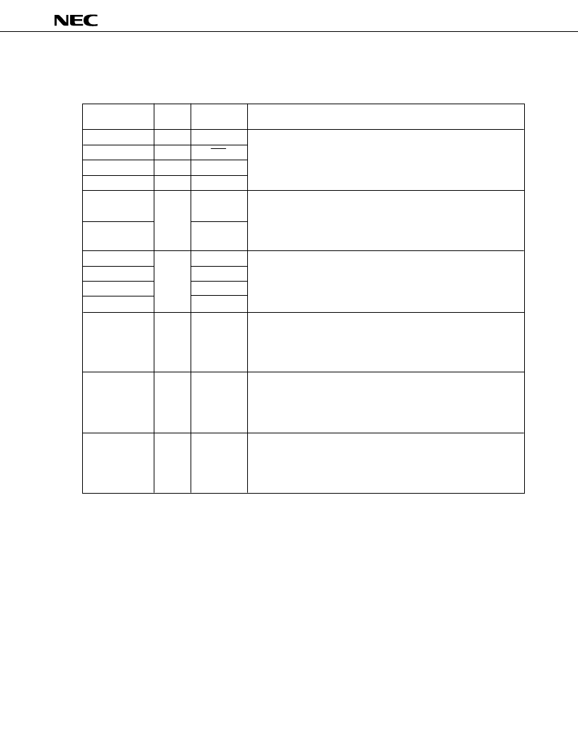
3. PIN FUNCTIONS
3.1 PORT PINS
Remarks 1.
The
μ
PD75402A(A) cannot perform 8-bit I/O with two ports as a pair.
2.
See Chapter 8 for each pin status during resetting.
Pin
P00
P01
P02
P03
P10
P12
P20
P21
P22
P23
P30 - P33
P50 - P53
P60 - P63
I/O
Input
I/O
I/O
Input
Input
I/O
I/O
I/O
I/O
Dual-
function pin
–
SCK
SO/SB0
SI
INT0
INT2
–
–
PCL
–
–
–
–
Function
4-bit input port (port 0)
P01 to P03 allow the connection of built-in pull-up resistors to be
specified in units of three bits by software.
2-bit input port (port 1)
P10 connects with the built-in noise eliminator using a sampling clock.
P12 connects with the built-in noise eliminator using an analog delay.
P12 allows the connection of built-in pull-up resistor to be specified by
software.
4-bit I/O port (port 2)
Allow I/O specification in units of four bits.
Allow the connection of built-in pull-up resistors to be specified in
units of four bits by software.
Programmable 4-bit I/O port (port 3)
Allow I/O specification bit by bit.
Allow the connection of built-in pull-up resistors to be specified in
units of four bits by software.
Can directly drive LED.
4-bit N-ch open-drain I/O port (port 5)
Allow I/O specification in units of four bits.
Allow the connection of built-in pull-up resistors to be specified bit by
bit by mask option.
Can directly drive LED.
4-bit I/O port (port 6)
Allow I/O specification in units of four bits.
Allow the connection of built-in pull-up resistors to be specified in
units of four bits by software.
Can directly drive LED.
相關PDF資料 |
PDF描述 |
|---|---|
| UPD75402AC | 4 BIT SINGLE-CHIP MICROCOMPUTER |
| UPD75402ACA | 4 BIT SINGLE-CHIP MICROCOMPUTER |
| UPD75402ACT | 4 BIT SINGLE-CHIP MICROCOMPUTER |
| UPD75402ACTA | 4 BIT SINGLE-CHIP MICROCOMPUTER |
| UPD75402AGB | 4 BIT SINGLE-CHIP MICROCOMPUTER |
相關代理商/技術參數(shù) |
參數(shù)描述 |
|---|---|
| UPD7554AG-597-E2 | 制造商:Renesas Electronics Corporation 功能描述: |
| UPD7554AG-597-E2-A | 制造商:Renesas Electronics Corporation 功能描述: |
| UPD7554AG-603-E2 | 制造商:Renesas Electronics Corporation 功能描述: |
| UPD7554AG-603-E2-A | 制造商:Renesas Electronics Corporation 功能描述: |
| UPD7554AG-611-E2 | 制造商:Renesas Electronics Corporation 功能描述: |
發(fā)布緊急采購,3分鐘左右您將得到回復。