- 您現(xiàn)在的位置:買賣IC網(wǎng) > PDF目錄358545 > VKA50MS12C (MURATA POWER SOLUTIONS INC) 1-OUTPUT 50.4 W DC-DC REG PWR SUPPLY MODULE PDF資料下載
參數(shù)資料
| 型號(hào): | VKA50MS12C |
| 廠商: | MURATA POWER SOLUTIONS INC |
| 元件分類: | 電源模塊 |
| 英文描述: | 1-OUTPUT 50.4 W DC-DC REG PWR SUPPLY MODULE |
| 封裝: | ROHS COMPLIANT, HALF BRICK PACKAGE-9 |
| 文件頁(yè)數(shù): | 4/4頁(yè) |
| 文件大?。?/td> | 276K |
| 代理商: | VKA50MS12C |
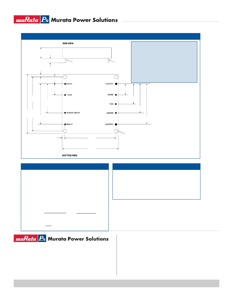
1.000
[25.40]
1.400
[35.56]
2.000
[50.80]
0.19 [4.8]
0.20 [5.1]
0.50 [12.7]
0.40 [10.16]
0.530 MAX
[13.46]
0.20 [5.1]
.040 [1.02] DIA.
7 PLACES
.081 [2.06] DIA.
2 PLACES
1.400
[35.56]
1.000
[25.40]
0.700
[17.78]
.400 [10.16]
1.900
[48.26]
2.28
[57.91]
MAX
MOUNTING INSERTS M3 X 0.5 THRU, 4 PLACES
MAX. TORQUE, 8 IN/LBS
2.40
[61.0]
MAX
MECHANICAL
Special attention should be given to the peak voltage
deviation during a dynamic load step when trimming the
output above the original set point to avoid tripping the
overvoltage protection circuit. Should an OVP condition
occur, the converter will go into a latch condition and
must be externally reset before it will return to normal
operation.
This feature allows the user to accurately adjust the module’s
output voltage set point to a specified level. This is achieved
by connecting a resistor or potentiometer from the TRIM
terminal to either the +Vout terminal (for increased Vout) or
the -Vout terminal (for decreased Vout). The formulae below
describe the trim resistor value to obtain a Vout change of
$
%. V
O
is output voltage prior to adjustment (3.3V, 5V, 12V,
15V, or 24V).
Radj - up =
(
Vo(100 +
$
%)
_
(100 + 2
$
%)
)
7
1.225
$
%
$
%
Radj - down =
(
100
-
2
)
7
$
%
NOTES:
All dimensions are in inches (millimeters).
PIN PLACEMENT TOLERANCE: ± 0.005”
MECHANICAL TOLERANCE: ± 0.015”
Marked with: specific modeL ordered, date code, job
code.
MATERIAL: Units are encapsulated in a low thermal
resistance molding compound which has excellent chemical
resistance and electrical properties in high humidity
environments and over a wide operating temperature
range. The encapsulant and outer shell of the unit have
UL94V-0 ratings. Lead material is solder plated to allow
ease of solderability.
OUTPUT ADJUST VOLTAGE
OVP NOTE
VKA50xSC
VKA50xSC.B01
Page 4 of 4
Technical enquiries
-
email:
mk@murata-ps.com,
tel:
+44 (0)1908 615232
www.murata-ps.com
VKA50xSC
50 Watt Single Output Half Brick DC/DC Converter
Murata Power Solutions, Inc. makes no representation that the use of its products in the circuits described herein, or the use of other
technical information contained herein, will not infringe upon existing or future patent rights. The descriptions contained herein do not imply
the granting of licenses to make, use, or sell equipment constructed in accordance therewith. Specifications are subject to change without
notice.
2008 Murata Power Solutions, Inc.
USA:
Canada:
Toronto, Tel: (866) 740 1232, email: toronto@murata-ps.com
UK:
Milton Keynes, Tel: +44 (0)1908 615232, email: mk@murata-ps.com
France:
Montigny Le Bretonneux, Tel: +33 (0)1 34 60 01 01, email: france@murata-ps.com
Germany:
München, Tel: +49 (0)89-544334-0, email: munich@murata-ps.com
Japan:
Tokyo, Tel: 3-3779-1031, email: sales_tokyo@murata-ps.com
Osaka, Tel: 6-6354-2025, email: sales_osaka@murata-ps.com
Website: www.murata-ps.jp
China:
Shanghai, Tel: +86 215 027 3678, email: shanghai@murata-ps.com
Guangzhou, Tel: +86 208 221 8066, email: guangzhou@murata-ps.com
Tucson (Az), Tel: (800) 547 2537, email: sales@murata-ps.com
Murata Power Solutions, Inc.
11 Cabot Boulevard, Mansfield, MA 02048-1151 U.S.A.
Tel: (508) 339-3000 (800) 233-2765 Fax: (508) 339-6356
www.murata-ps.com email: sales@murata-ps.com
ISO 9001 REGISTERED
07/28/08
相關(guān)PDF資料 |
PDF描述 |
|---|---|
| VKA51A2-1M | Crystal Oscillator |
| VKA51A2-52M | Crystal Oscillator |
| VKA52A2-1M | Crystal Oscillator |
| VKA52A2-52M | Crystal Oscillator |
| VKA53A2-1M | Crystal Oscillator |
相關(guān)代理商/技術(shù)參數(shù) |
參數(shù)描述 |
|---|---|
| VKA50MS15 | 功能描述:DC/DC轉(zhuǎn)換器 50W 48V TO 15V 3.3A RoHS:否 制造商:Murata 產(chǎn)品: 輸出功率: 輸入電壓范圍:3.6 V to 5.5 V 輸入電壓(標(biāo)稱): 輸出端數(shù)量:1 輸出電壓(通道 1):3.3 V 輸出電流(通道 1):600 mA 輸出電壓(通道 2): 輸出電流(通道 2): 安裝風(fēng)格:SMD/SMT 封裝 / 箱體尺寸: |
| VKA50MS15-1 | 制造商:未知廠家 制造商全稱:未知廠家 功能描述:Analog IC |
| VKA50MS15-1C | 功能描述:DC/DC轉(zhuǎn)換器 VKA50MS15-1C RoHS:否 制造商:Murata 產(chǎn)品: 輸出功率: 輸入電壓范圍:3.6 V to 5.5 V 輸入電壓(標(biāo)稱): 輸出端數(shù)量:1 輸出電壓(通道 1):3.3 V 輸出電流(通道 1):600 mA 輸出電壓(通道 2): 輸出電流(通道 2): 安裝風(fēng)格:SMD/SMT 封裝 / 箱體尺寸: |
| VKA50MS15-6 | 制造商:未知廠家 制造商全稱:未知廠家 功能描述:Analog IC |
| VKA50MS15-61 | 制造商:未知廠家 制造商全稱:未知廠家 功能描述:Analog IC |
發(fā)布緊急采購(gòu),3分鐘左右您將得到回復(fù)。